Digital receiver and optical communication system that uses same

a digital receiver and optical communication technology, applied in the field of digital receivers and optical communication systems, can solve the problems of difficult balance between high resolution and high speed, high cost, and so as to prevent physical lack of resolution of analog-to-digital converters from deteriorating the reception precision of digital receivers

Active Publication Date: 2014-03-25
NEC CORP
View PDF21 Cites 6 Cited by
  • Summary
  • Abstract
  • Description
  • Claims
  • Application Information

AI Technical Summary

Benefits of technology

[0014]According to an aspect of this invention, a discrimination level used for analog-to-digital conversion is controlled and a gap between a transfer function of an analog-to-digital converter which is dependent on the discrimination level and an initial transfer function is cancelled, to thereby improve the effective resolution of the analog-to-digital converter and prevent a physical lack of resolution of the analog-to-digital converter from deteriorating the reception precision of a digital receiver.

Problems solved by technology

Coupled with limitations to circuit speed and power consumption, this makes it difficult in the related AD converter to exert high-precision control for maintaining equally spaced discrimination levels, and is a reason that balancing high resolution and high speed is not easy.
An AD converter that lacks in resolution makes waveform distortion compensation by DSP unsatisfactory particularly when the optical signal-to-noise ratio (SNR) is low, when a high degree of dispersion is applied, when multi-level modulation is used, or the like, and deteriorates system performance.

Method used


Image

  • Digital receiver and optical communication system that uses same
  • Digital receiver and optical communication system that uses same
  • Digital receiver and optical communication system that uses same

Examples


first embodiment

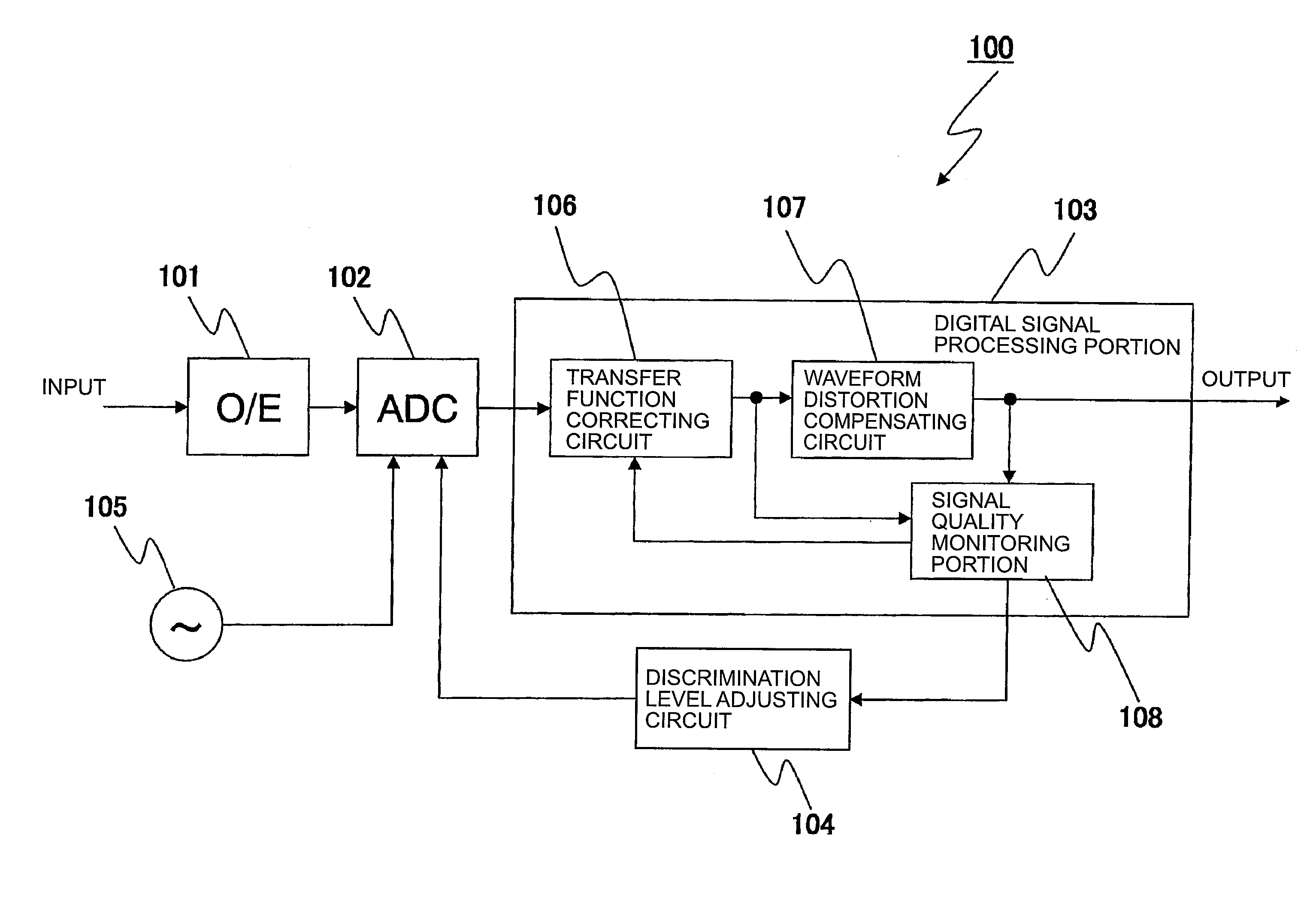
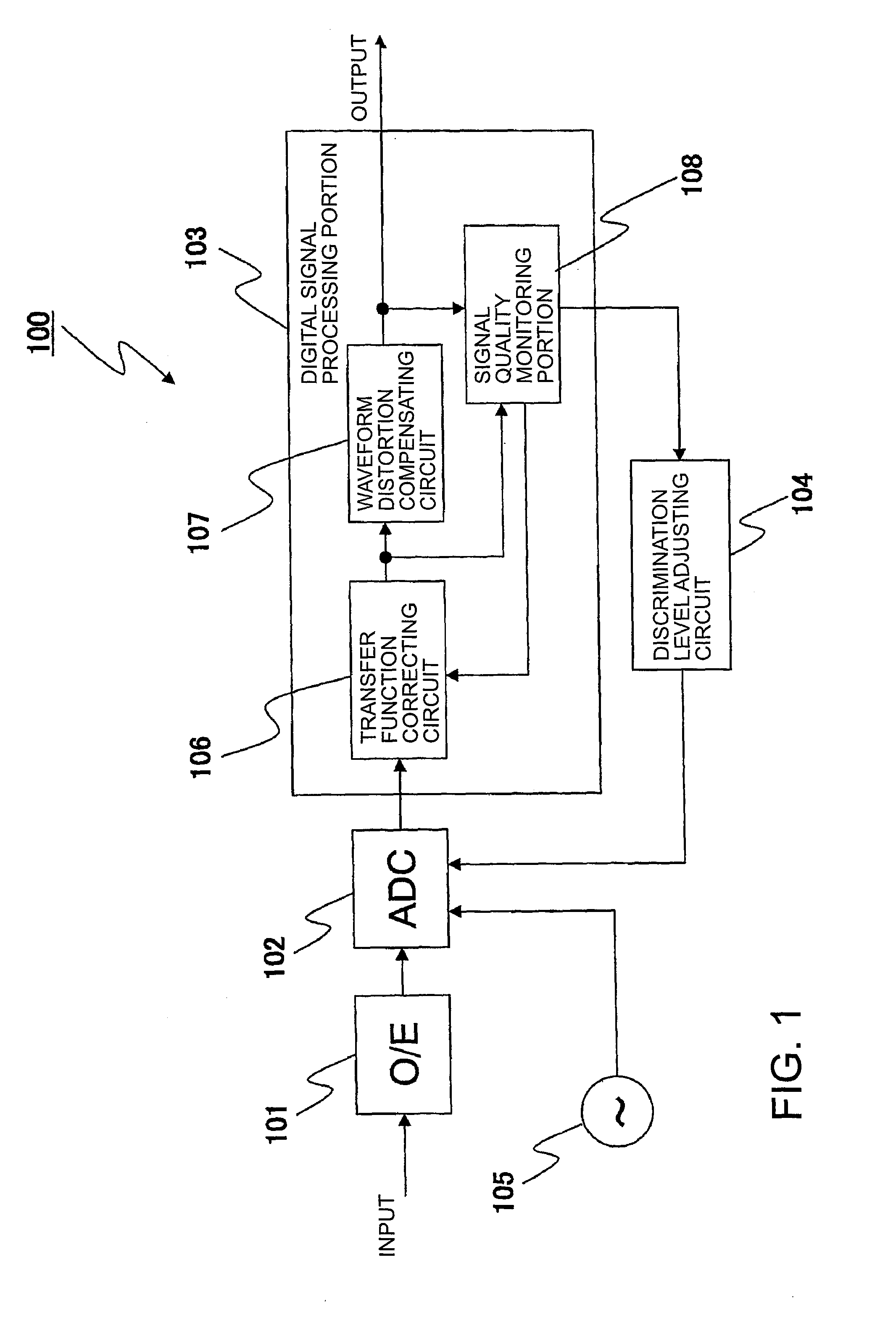
[0039]FIG. 1 illustrates the schematic configuration of a digital receiver according to this invention. The illustrated digital receiver 100, includes an optical-to-electrical (OE) converter 101, an analog-to-digital (AD) converter (ADC) 102, a digital signal processing portion 103, a discrimination level adjusting circuit 104, and an AD converter discrimination clock 105.

[0040]The optical-to-electrical converter 101 converts an optical input signal into an analog electrical signal.

[0041]The AD converter 102 converts an analog electrical signal (analog input signal) into a digital signal. The AD converter 102 also sets a plurality of discrimination levels used as a criterion in AD conversion in accordance with a discrimination level control signal from the discrimination level adjusting circuit 104. The AD converter 102 thus functions as analog-to-digital conversion means for setting discrimination levels in accordance with the discrimination level control signal, converting an anal...

second embodiment

[0061]A digital receiver according to this invention is described next.

[0062]FIG. 4 is a block diagram illustrating the schematic configuration of the digital receiver according to this embodiment. Components that are the same as those of the digital receiver of FIG. 1 are denoted by the same symbols in order to omit descriptions thereof.

[0063]The digital receiver of FIG. 4 which is denoted by 300 uses a Dual Polarization (DP)-QPSK signal as an input signal. The input signal is given to the digital receiver 300 via an optical transmission path 301, which is a dispersing medium.

[0064]The digital receiver 300 includes, as illustrated, a local oscillator light source 302, a pair of polarization beam splitters (PBSs) 303-1 and 303-2, a pair of 90°-hybrids 304-1 and 304-2, a local oscillator light phase monitor 305, and a local oscillator light phase adjusting portion 306.

[0065]The digital receiver 300 also includes four optical-to-electrical converters 101-1 to 101-4, four analog-to-dig...

third embodiment

[0089]A digital receiver according to this invention is described next with reference to FIG. 7. In FIG. 7, components that are the same as those of the digital receiver of FIG. 4 are denoted by the same symbols in order to omit descriptions thereof.

[0090]The signal quality monitoring portion 108 of the digital receiver 600 illustrated in FIG. 7 includes a level distribution / gradient estimating portion 601, a waveform equalization error monitor 602, and a bit error rate (BER) monitor 603.

[0091]The level distribution / gradient estimating portion 601 doubles as the waveform monitoring portion 308 and level distribution / gradient estimating portion 307 of FIG. 4.

[0092]The waveform equalization error monitor 602 monitors a difference between the waveform of an output signal that is output from the waveform distortion compensating circuit 107 and an ideal waveform, namely, a waveform equalization error. The BER monitor 603 monitors the bit error rate of the output signal. The waveform equa...


PUM


Abstract

A digital receiver includes: an analog-to-digital (AD) converter (102) for setting discrimination levels in accordance with a discrimination level control signal and converting an analog input signal into a digital signal based on the set discrimination levels; a discrimination level adjusting circuit (104) for generating the discrimination level control signal and outputting the discrimination level control signal to the AD converter; a signal quality monitoring portion (108) for generating a transfer function correction control signal, which is information about a transfer function of the AD converter; and a transfer function correcting circuit (106) for performing signal processing on the digital signal so as to cancel a gap between the transfer function of the AD converter and an initial transfer function based on the transfer function correction control signal.

Description

CROSS REFERENCE TO RELATED APPLICATIONS[0001]This application is a National Stage of International Application No. PCT / JP2011 / 054821 filed Feb. 24, 2011, claiming priority based on Japanese Patent Application Nos. 2010-058686 filed Mar. 16, 2010, and 2010-225668 filed Oct. 5, 2010, the contents of all of which are incorporated herein by reference in their entirety.TECHNICAL FIELD[0002]This invention relates to a digital receiver and an optical communication system that uses the digital receiver, and more particularly, to a digital receiver that employs digital coherent reception method and an optical communication system that uses the digital receiver.BACKGROUND ART[0003]In recent years, the importance of the digital coherent optical communication technology is increasing as the demand for faster networks with larger capacity grows. This communication method, also called intradyne reception, realizes a receiving sensitivity improved by 3 to 6 dB or more from On-Off Keying (OOK), Dif...

Claims


Application Information

Patent Timeline
Patent Type & Authority Patents(United States)
IPC IPC(8): H03M1/10H04B10/69H04B10/60
CPCH04B10/60H04B10/695H03M1/1061H03M1/12H03M1/1235
Inventor ABE, JUNICHINOGUCHI, HIDEMI
Owner NEC CORP
Why Eureka
Try Eureka