Charging apparatus and charging/discharging apparatus including temperature adjusting element of secondary battery for buffering

a charging apparatus and temperature adjustment technology, applied in the direction of secondary cell servicing/maintenance, primary cell maintenance/service, safety/protection circuit, etc., can solve the problems of reducing testing efficiency, charging apparatus likely to be affected by ambient temperature, above-described conventional charging apparatus and charging/discharging apparatus, etc., to reduce cell thickness, improve heat conductivity, and fast control

Inactive Publication Date: 2014-04-08
NEC CORP
View PDF28 Cites 14 Cited by
  • Summary
  • Abstract
  • Description
  • Claims
  • Application Information

AI Technical Summary

Benefits of technology

[0016]Furthermore, a charging / discharging apparatus according to the present invention comprises a secondary battery for buffering, a current supply section, a connection section, a switching control section, and temperature adjusting means. The current supply section supplies power to the secondary battery used for buffering. The connection section is connected to a secondary battery to be charged and discharged. The switching control section switches a mode of the charging / discharging apparatus between a first mode in which power supplied by the power supply section is accumulated in the secondary battery used for buffering and a second mode in which the secondary battery to be charged and discharged is charged with the power supplied by the secondary battery used for buffering and a third mode in which the power accumulated in the secondary battery to be charged and discharged is discharged to the secondary battery used for buffering. The temperature adjusting means adjusts the temperature of the secondary battery used for buffering from outside of the secondary battery used for buffering. The secondary battery used for buffering includes at least one cell comprising a battery element with a positive electrode plate and a negative electrode plate laminated, the battery element being sealed with an outer cover film. As described above, the charging apparatus and charging / discharging apparatus according to the present invention includes the temperature adjusting means, which adjusts the temperature of the secondary battery used for buffering from outside of the secondary battery used for buffering. Furthermore, the secondary battery used for buffering includes the at least one cell comprising the battery element which includes the laminated positive and negative electrode plates and which is sealed with the outer cover film. The thermal capacity of the outer cover of the cell is negligibly smaller than that of the outer cover (can) of a conventional secondary battery. Moreover, the battery element is thinner than a wound battery element. As a result, the heat conductivity of the cell is improved, and the temperature of the battery element can be quickly controlled to the desired temperature from outside of the battery element. Furthermore, the reduced thickness of the cell allows the temperature of the battery element as a whole to be controlled to a uniform value. Thus, the temperature of the secondary battery used for buffering can be easily managed.
[0017]The present invention can inhibit a possible variation in the electrical characteristics of the secondary battery used for buffering resulting from a variation in the temperature of the secondary battery used for buffering. The present invention can also reduce the startup time required to allow the secondary battery used for buffering to exhibit desired electrical characteristics. As a result, the present invention can solve the thermal problems with the apparatuses in which the secondary battery used for buffering is mounted to charge or charge and discharge the target secondary battery.

Problems solved by technology

However, the above-described conventional charging apparatus and charging / discharging apparatus pose problems described below.
Thus, the charging apparatus is likely to be affected by ambient temperature.
However, the charging / discharging apparatus disclosed in Japanese Patent Laid-Open No. 9-159738 has disadvantages described below in connection with on accurate evaluation of the charging / discharging characteristics.
However, in this case, a long time is required to wait for the temperature to become lower, thus reducing testing efficiency.
In particular, if the charging / discharging apparatus is used in the process of manufacturing the secondary battery, the manufacturing efficiency of the secondary battery is reduced.
However, if the can is used as an outer cover, heat outside the can has difficulty being transmitted to an internal battery element.
Furthermore, the thermal capacity of the can cannot be neglected.
Moreover, producing a secondary battery having a thickness of at most 3 mm is difficult owing to processing limits on metal plates.
For the above-described reasons, it is difficult to control the temperature of the battery element inside the can over a short span or to control the temperature of the entire battery element to a uniform value.

Method used


Image

  • Charging apparatus and charging/discharging apparatus including temperature adjusting element of secondary battery for buffering
  • Charging apparatus and charging/discharging apparatus including temperature adjusting element of secondary battery for buffering
  • Charging apparatus and charging/discharging apparatus including temperature adjusting element of secondary battery for buffering

Examples


exemplary embodiment 1

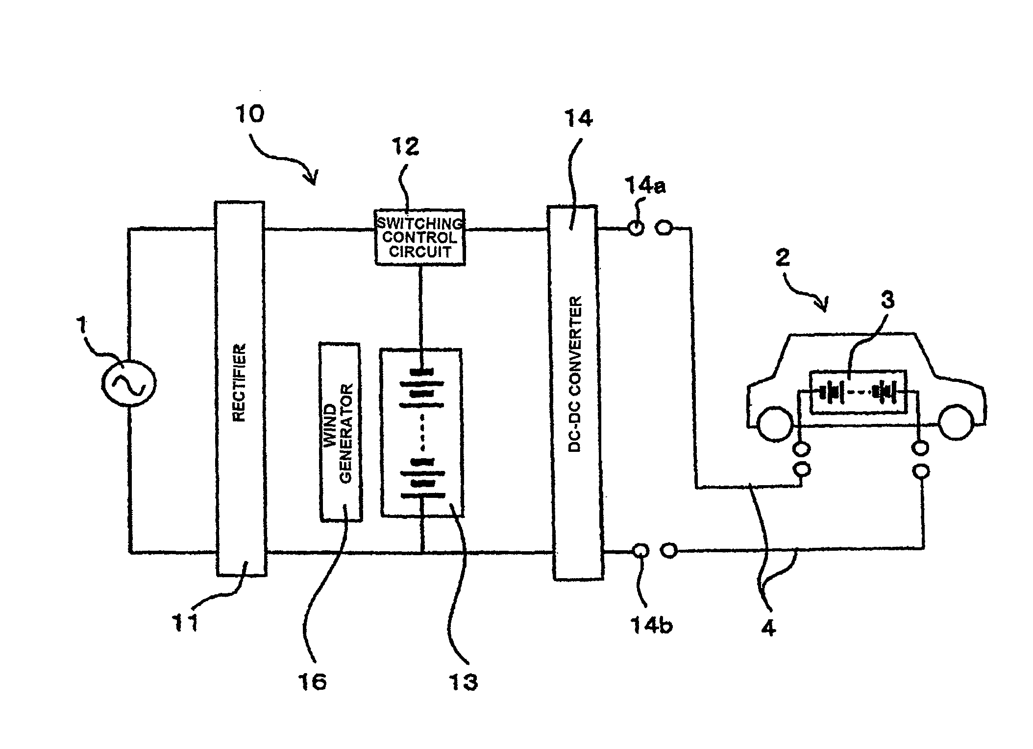
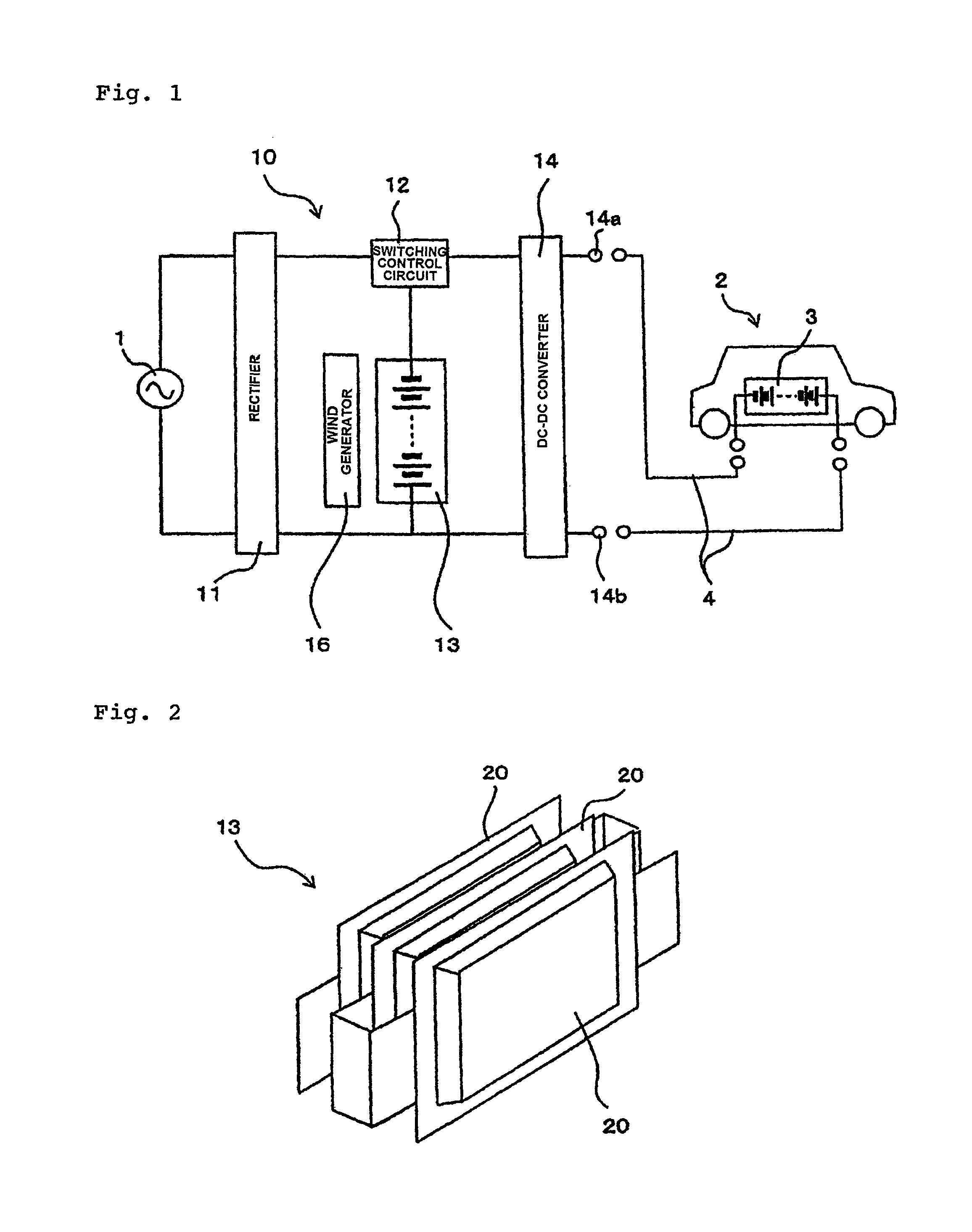
[0024]Now, a first exemplary embodiment of the present invention will be described with reference to the drawings. FIG. 1 is a block diagram of a charging apparatus according to the present exemplary embodiment. The illustrated charging apparatus is used to charge a driving battery in an electric vehicle.

[0025]Charging apparatus 10 includes rectifier 11, secondary battery 13 used for buffering, isothermal wind generator 16, switching control circuit 12, and DC-DC converter 14. Charging cables 4 are connected to output terminals 14a and 14b of DC-DC converter 14. Driving battery 3 mounted in electric vehicle 2 is charged by connecting charging cables 4 to driving battery 3.

[0026]Rectifier 11 is a device that converts alternating current power loaded from commercial alternating current power source 1 into direct current power to supply the direct current power to secondary battery 13 used for buffering. Rectifier 11 functions as a current supply section according to the present invent...

second embodiment

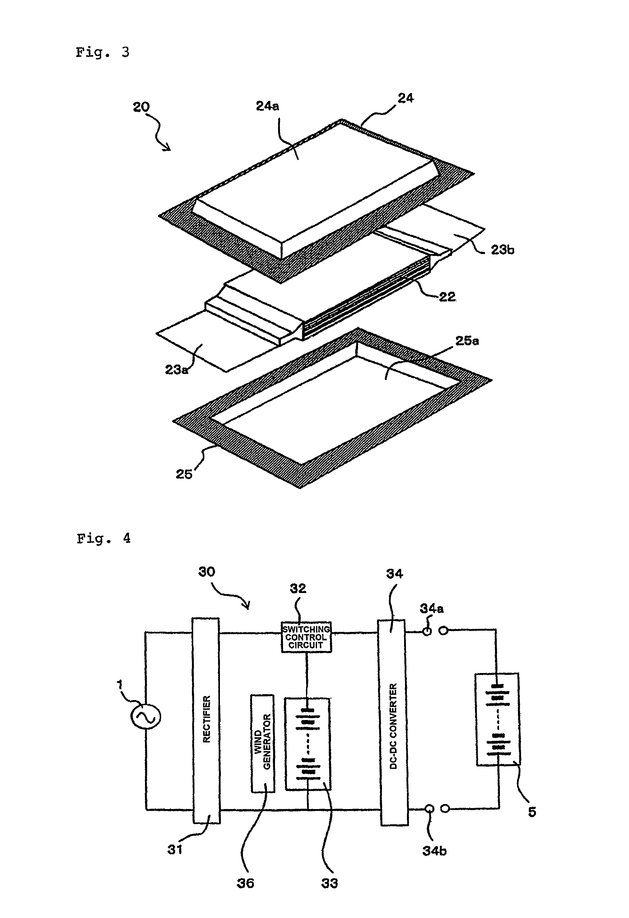
[0054]Now, a second embodiment of the present invention will be described with reference to the drawings. FIG. 4 is a block diagram of a charging / discharging apparatus according to the present exemplary embodiment. The illustrated charging-discharging apparatus is used to test the secondary battery for charging / discharging characteristics during the manufacturing process.

[0055]Charging / discharging apparatus 30 according to the present exemplary embodiment includes rectifier 31, secondary battery 33 used for buffering, isothermal wind generator 36, switching control circuit 32, and DC-DC converter 34. Secondary battery 5 used for testing is connected to output terminals 34a and 34b of DC-DC converter 34 to test secondary battery 5 used for testing for the charging / discharging characteristics.

[0056]Rectifier 31, secondary battery 33 used for buffering, isothermal wind generator 36, and DC-DC converter 34 are similar to those described in the first embodiment and thus will not be descr...


PUM


Abstract

Charging apparatus 10 includes secondary battery 13 used for buffering, rectifier 11 that supplies direct current power to secondary battery 13 used for buffering, DC-DC converter 14 connected to driving battery 3 in electric vehicle 2 via charging cable 4, switching control circuit 12, and isothermal wind generator 16 that adjusts the temperature of secondary battery 13 used for buffering from outside of secondary battery 13 used for buffering. Switching control circuit 12 switches charging apparatus 10 between a first mode in which power supplied by rectifier 11 is accumulated in secondary battery 13 used for buffering and a second mode in which driving battery 3 is charged with the power supplied by secondary battery 13 used for buffering. Secondary battery 13 used for buffering includes at least one cell in which a battery element with a positive electrode plate and a negative electrode plate that are laminated therein is sealed with an outer cover film.

Description

TECHNICAL FIELD[0001]The present invention relates to a charging apparatus and a charging-discharging apparatus for a secondary battery, and in particular, to a charging apparatus and a charging-discharging apparatus for a film covered laminate battery in which a positive electrode and a negative electrode are laminated and sealed with an outer cover material.BACKGROUND ART[0002]Secondary batteries can be repeatedly used by means of charging and are thus used as power sources for various electric apparatuses. Moreover, in recent years, high-capacity secondary batteries have also been developed and used as power sources for hybrid and electric vehicles. Furthermore, various improvements have been made on a charging apparatus for charging a secondary battery and on a charging apparatus with a discharging function.[0003]For example, one capability that is required for charging apparatuses is a reduction in charging time. The reduction in charging time is particularly important for a ch...

Claims


Application Information

Patent Timeline
Patent Type & Authority Patents(United States)
IPC IPC(8): H02J7/00
CPCH01M10/44B60L2210/10Y02T10/7216Y02T90/14H01M6/5033H02J7/027B60L11/1816Y02E60/12H01M10/5083B60L11/185Y02T10/92Y02T10/7055Y02T10/705H01M10/5032H01M10/5016H01M10/5006Y02T90/127B60L3/0046Y02T90/121Y02T10/7094Y02T90/128Y02T10/7005B60L11/1872B60L11/1811H01M10/5044H02J7/0054B60L11/1874H01M10/5085H02J7/0014H01M10/5067H01M10/5004H01M10/615H01M10/6572H01M10/647H01M10/6571H01M10/6563H01M10/613H01M10/655H01M10/625Y02T10/7072B60L53/14B60L53/20B60L53/11B60L58/25B60L58/26H02J7/342B60L58/24Y02T10/70Y02T10/72Y02E60/10H02J7/02H02J7/0048H02J7/00309H02J7/00Y02T90/12
Inventor SAITO, TAKASHIUTSUMI, KAZUAKI
Owner NEC CORP
Why Eureka
Try Eureka