Acoustic wave resonator and duplexer using same

a technology of acoustic wave resonator and duplexer, which is applied in the direction of impedence network, electrical apparatus, electromechanical/electrostrictive/magnetostrictive devices, etc., can solve the problems of generating more transverse-mode spurious emission of conventional acoustic wave resonators, acoustic wave filters using this type of piezoelectric bodies typically have a disadvantage of poor temperature characteristics, and achieve the effect o

Active Publication Date: 2014-04-15
SKYWORKS PANASONIC FILTER SOLUTIONS JAPAN
View PDF12 Cites 16 Cited by
  • Summary
  • Abstract
  • Description
  • Claims
  • Application Information

AI Technical Summary

Benefits of technology

[0013]Such a configuration of an acoustic wave resonator reduces transverse-mode waves in the IDT cross region to prevent transverse-mode spurious emission.

Problems solved by technology

However, an acoustic wave filter using this type of piezoelectric body typically has a disadvantage of poor temperature characteristics.
As shown in FIG. 32, however, conventional acoustic wave resonator 101 disadvantageously generates more transverse-mode spurious emission between the resonance frequency and the antiresonance frequency.

Method used


Image

  • Acoustic wave resonator and duplexer using same
  • Acoustic wave resonator and duplexer using same
  • Acoustic wave resonator and duplexer using same

Examples


first exemplary embodiment

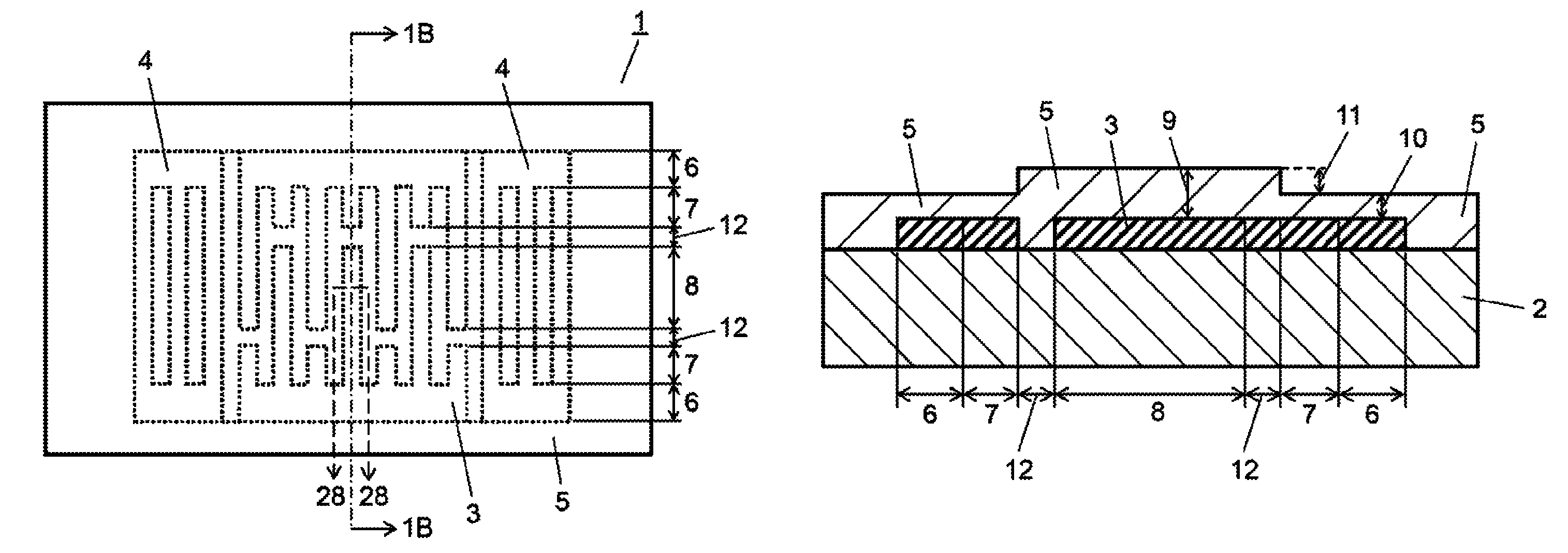
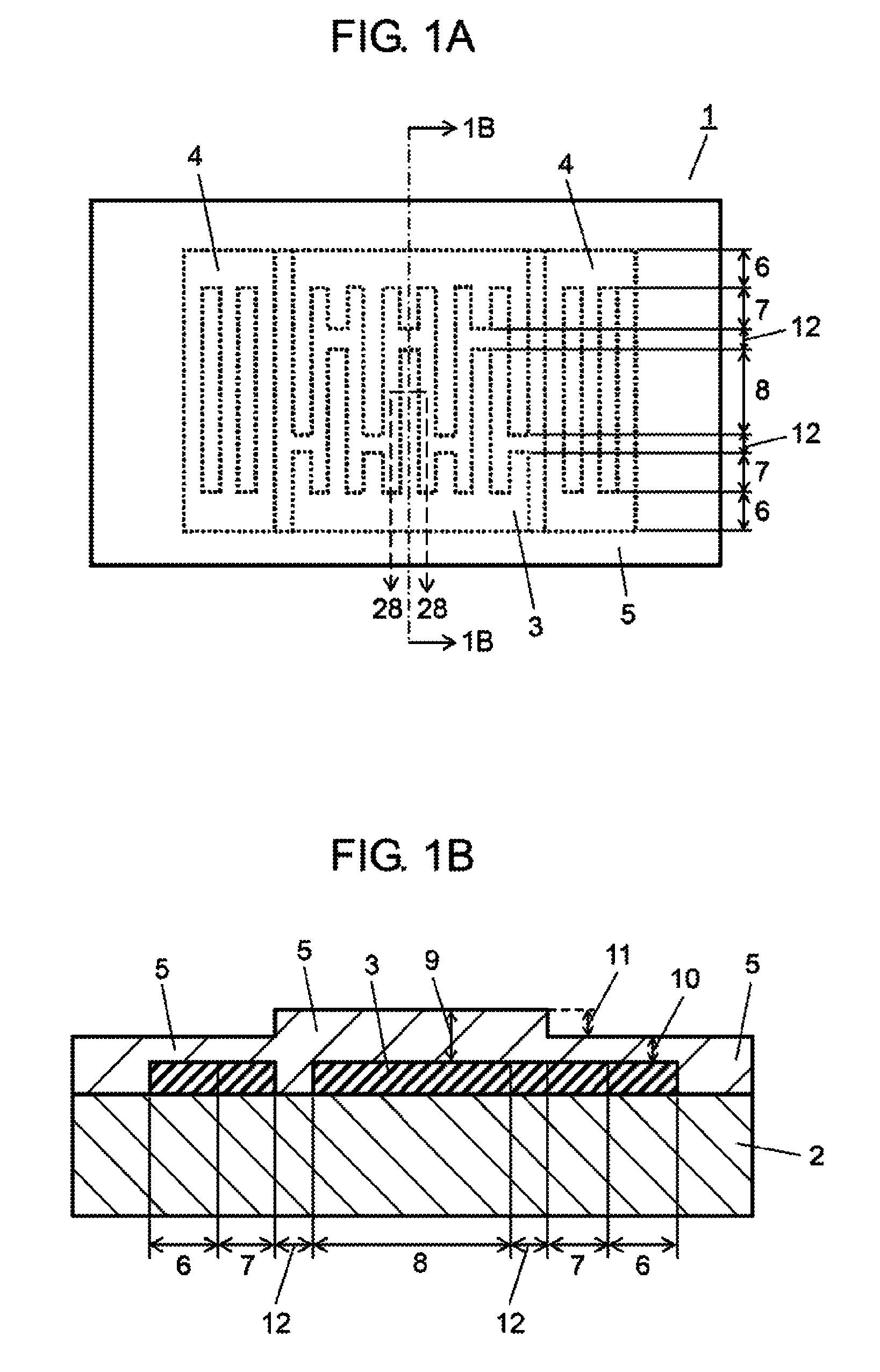
[0074]Hereinafter, a description is made of the first exemplary embodiment of the present invention using the related drawings. FIG. 1A is a top view of an acoustic wave resonator according to the first embodiment; FIG. 1B is a cross sectional (a cross section along the direction in which the electrode fingers of IDT electrode 3 extend) view of the acoustic wave resonator, taken along line 1B-1B in FIG. 1A.

[0075]In FIGS. 1A and 1B, acoustic wave resonator 1 includes piezoelectric body 2; IDT electrode 3 provided on piezoelectric body 2, for exciting an acoustic wave with wavelength λ; grating reflector 4 provided on piezoelectric body 2 so as to interpose IDT electrode 3; and dielectric thin film 5 provided on piezoelectric body 2 so as to cover IDT electrode 3 and grating reflector 4.

[0076]Piezoelectric body 2 is a substrate based on lithium niobate (LiNbO3); however, body 2 may be another piezoelectric single-crystal medium such as a substrate or thin film based on crystal, lithiu...

second exemplary embodiment

[0101]Next, a description is made of acoustic wave resonator 1 of the second exemplary embodiment using the related drawings. The configuration is the same as that of the first embodiment unless particularly described. FIG. 12A is a top view of acoustic wave resonator 1 according to the second embodiment; FIG. 12B is a cross sectional (a cross section along the direction in which the electrode fingers of IDT electrode 3 extend) view of the acoustic wave resonator, taken along line 12B-12B in FIG. 12A.

[0102]As shown in FIGS. 12A and 12B, acoustic wave resonator 1 of the second embodiment does not have a dummy electrode, and the entire region interposed between bus bar electrode region 6 and IDT cross region 8 becomes gap region 12. Here as well, normalized film thickness 10 of dielectric thin film 5 above a part of at least one (both in FIG. 12) of bus bar electrode region 6 and gap region 12 (the side of bus bar electrode region 6) is configured to be smaller than normalized film th...

third exemplary embodiment

[0105]Next, a description is made of acoustic wave resonator 1 of the third exemplary embodiment using the related drawings. The configuration is the same as that of the first embodiment unless particularly described. FIG. 13 is a cross sectional (a cross section of IDT cross region 8) view, taken along line 13-13 in FIG. 1A according to the first embodiment or line 13-13 in FIG. 12A according to the second embodiment.

[0106]In acoustic wave resonator 1 of FIG. 13, piezoelectric body 2 is based on lithium niobate (LiNbO3), and the Euler angle (φ, θ, ψ) of this piezoelectric body 2 satisfies −100°≦θ≦−60°, 1.193φ−2°≦ψ≦1.193φ+2°, ψ≦−2φ−3°, −2φ+3°≦ψ where φ and θ are cut-out angles of piezoelectric body 2; ψ is the propagation angle of a main acoustic wave in IDT electrode 3 on piezoelectric body 2.

[0107]Here, piezoelectric body 2 based on lithium niobate is a trigonal crystal, and thus the Euler angle has the next relationship.

[0108](φ,θ,Ψ)=⁢(60+φ,-θ,Ψ)=⁢(60-φ,-θ,180-Ψ)=⁢(φ,180+θ,180-Ψ)...


PUM


Abstract

An acoustic wave resonator includes a piezoelectric body, an IDT electrode for exciting an acoustic wave with wavelength λ, and a dielectric thin film provided so as to cover the IDT electrode. The IDT electrode includes a bus bar electrode region, a dummy electrode region, and an IDT cross region in order from outside. The film thickness of the dielectric thin film above at least one of the bus bar electrode region and the dummy electrode region is smaller than that above the IDT cross region by 0.1λ to 0.25λ. This configuration provides an acoustic wave resonator that reduces transverse-mode spurious emission.

Description

[0001]This application is a U.S. national phase application of PCT international application PCT / JP2010 / 003459, filed May 24, 2010.TECHNICAL FIELD[0002]The present invention relates to an acoustic wave resonator and a duplexer using the resonator.BACKGROUND ART[0003]Conventionally, a piezoelectric body has been used with a large electromechanical coupling factor such as a lithium niobate (LiNbO3) substrate to achieve an acoustic wave filter with wide-band characteristics.[0004]However, an acoustic wave filter using this type of piezoelectric body typically has a disadvantage of poor temperature characteristics. To improve temperature characteristics, a way is devised in which a dielectric thin film made of SiO2 is formed on a piezoelectric body made of lithium niobate.[0005]FIGS. 31A and 31B show a configuration of a conventional acoustic wave resonator. FIG. 31A is a top view of the resonator, and FIG. 31B is a sectional view of the resonator, taken along line 31B-31B in FIG. 31A.[...

Claims


Application Information

Patent Timeline
Patent Type & Authority Patents(United States)
IPC IPC(8): H03H9/64H03H9/00
CPCH03H9/02858H03H9/14526H03H9/02559H03H9/1452H03H9/02834H03H9/6496H03H9/725H03H9/02984H03H9/02992H03H9/1457
Inventor NAKANISHI, HIDEKAZUNAKAMURA, HIROYUKITSURUNARI, TETSUYAGOTO, REIFUJIWARA, JOJI
Owner SKYWORKS PANASONIC FILTER SOLUTIONS JAPAN
Why Eureka
Try Eureka