
Wireless motion capture test head system

a motion capture and test head technology, applied in the field of mounts, can solve the problems of inability to disclose the wireless motion capture element of the current system, the type of sensor generally not used in the test environment, and the cost of existing headform acceleration test systems, etc., and achieve the effect of easy decoupling, connecting and disconnecting

Active Publication Date: 2014-04-15
NEWLIGHT CAPITAL LLC
View PDF198 Cites 14 Cited by
  • Summary
  • Abstract
  • Description
  • Claims
  • Application Information

AI Technical Summary

Benefits of technology

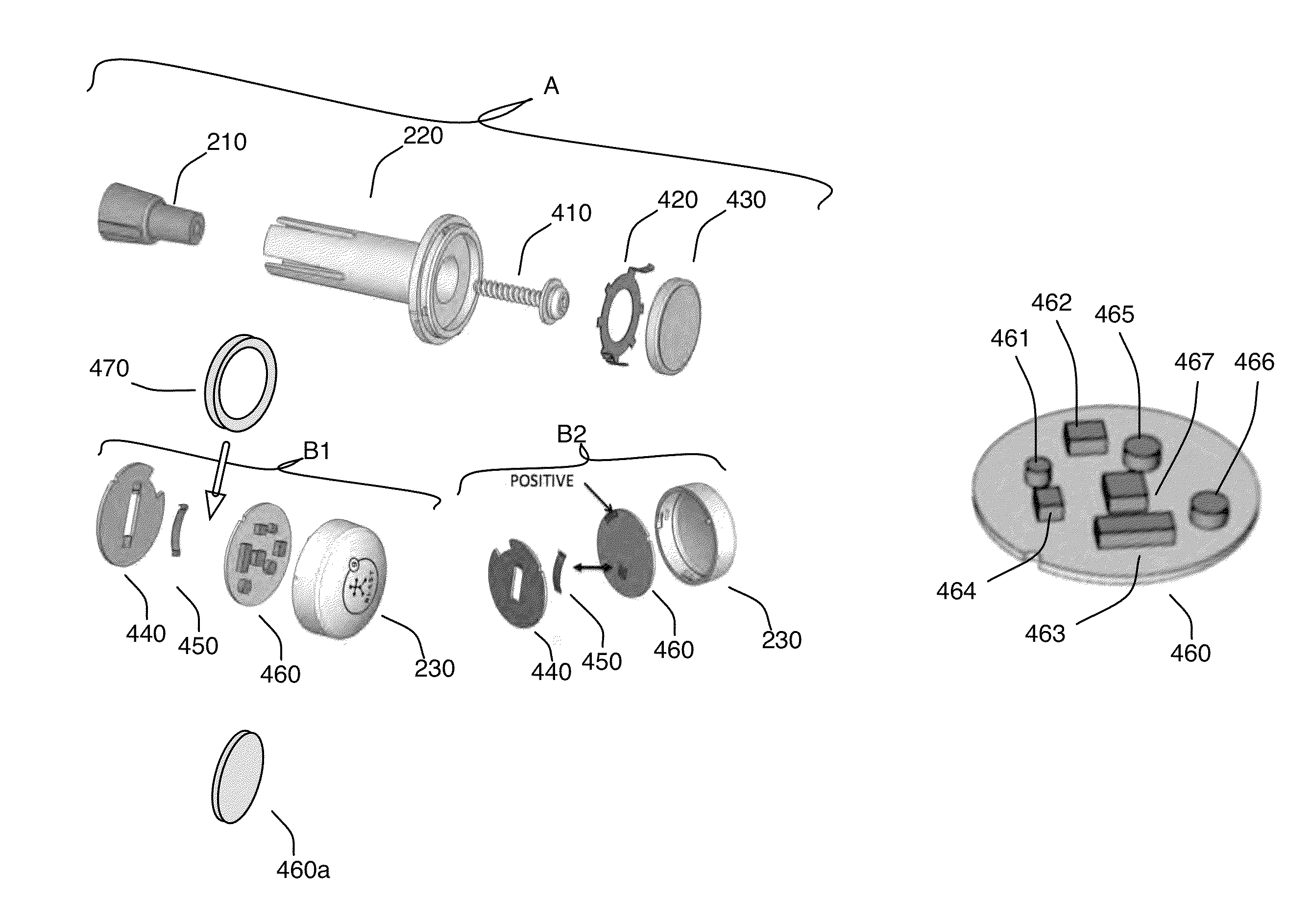
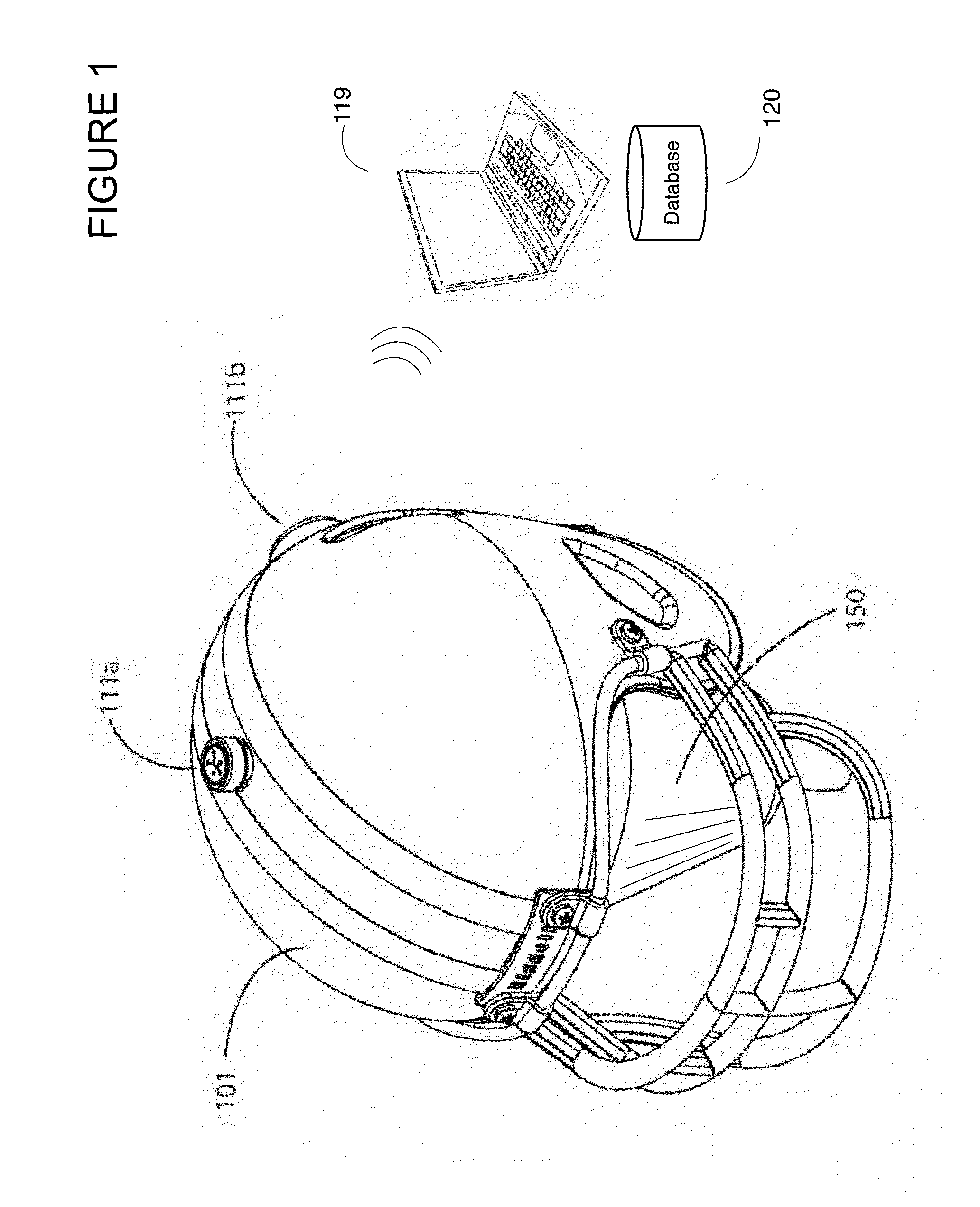
The invention is a wireless motion capture test head system that allows for the capture of motion and acceleration of a person's head. The system includes a motion capture element, an isolator, and a mount that securely attaches the motion capture element to the isolator. The isolator reduces the transfer of acceleration to the person's brain, minimizing power and storage requirements. The system can be retrofitted to existing headforms or headgear, and a visual marker can be included for visually tracking motion. The weight of the system is minimized to match the weight of the person's brain. The technical effects of the invention include improved accuracy and efficiency in motion capture testing.

Problems solved by technology

Existing headform acceleration test systems, for example, may cost upwards of $60,000 and are impractical for most users to purchase.
These types of sensors generally have not been utilized in test environments with headforms for example.
Disadvantages of current systems appear to include the use of wire-based sensors and electronics transmitting sensor data in a wired-manner.
Generally, current systems lack any disclosure of a wireless motion capture element coupled to headform of a dummy, that may retrofitted on various types of headgear.
In addition, current systems appear to lack the use of an isolator, as part of a wireless motion capture system, that may simulate physical acceleration dampening of cerebrospinal fluid around a human brain, in order to minimize translation of linear acceleration and rotational acceleration of the event data to obtain an observed linear acceleration and an observed rotational acceleration of the at least one motion capture element coupled in an inner portion of a headform, separate from a helmet.
However, it appears as though Alderson lacks any disclosure of any wireless sensors coupled to the headform of a dummy to detect one or more of a linear force and a rotational force.
In addition, the system appears to lacks any disclosure of a wireless motion capture element, coupled with a headform, including an isolator such that the motion capture system may simulate physical acceleration dampening of cerebrospinal fluid around a human brain, from the headform.
As such, the system appears to lack any disclosure of a wireless motion capture sensor, coupled to a headform of a dummy, for detecting linear and rotational forces, in a wireless manner, and wireless transmitting the data to a microcontroller, not during game play.
In addition, the system appears to lacks any disclosure of an isolator such that the motion capture system may simulate physical acceleration dampening of cerebrospinal fluid around a human brain, from the headform.
Such a system, however, appears to lack any disclosure of a wireless motion capture element coupled to a headform of a dummy, for example, wherein the wireless motion capture system includes an isolator, such that the motion capture system may simulate physical acceleration dampening of cerebrospinal fluid around a human brain, in order to minimize translation of linear acceleration and rotational acceleration of the event data to obtain an observed linear acceleration and an observed rotational acceleration of the at least one motion capture element coupled in an inner portion of a headform, separate from a helmet.
In addition, the system appears to lacks any disclosure of a wireless motion capture element, coupled with a headform, including an isolator such that the motion capture system may simulate physical acceleration dampening of cerebrospinal fluid around a human brain, from the headform.
Furthermore, the system of Mack appears to lack an isolator such that a motion capture system may simulate physical acceleration dampening of cerebrospinal fluid around a human brain, from the headform.
However, it appears as though the system of Chu et al. lacks any disclosure of a wireless motion capture element, coupled with a headform, including an isolator such that the motion capture system may simulate physical acceleration dampening of cerebrospinal fluid around a human brain, from the headform.

Method used


Image

  • Wireless motion capture test head system
  • Wireless motion capture test head system
  • Wireless motion capture test head system

Examples


Embodiment Construction

[0037]A wireless motion capture test head system will now be described. In the following exemplary description numerous specific details are set forth in order to provide a more thorough understanding of the ideas described throughout this specification. It will be apparent, however, to an artisan of ordinary skill that embodiments of ideas described herein may be practiced without incorporating all aspects of the specific details described herein. In other instances, specific aspects well known to those of ordinary skill in the art have not been described in detail so as not to obscure the disclosure. Readers should note that although examples of the innovative concepts are set forth throughout this disclosure, the claims, and the full scope of any equivalents, are what define the invention. One skilled in the art will recognize that embodiments of the invention may be utilized in any headgear equipment capable of coupling with the apparatus. This includes any piece of sporting hea...


PUM


Abstract

A wireless motion capture test head system including at least one motion capture element, an isolator, mount and an external computer. The motion capture element(s) may include a memory, a wireless motion capture sensor, a radio and a microcontroller. The microcontroller may collect sensor values data from the wireless motion capture sensor, store the data in the memory, analyze the data, recognize an event within the data to determine event data, and transmit the event data associated with the event via the radio. The isolator may surround the at least one motion capture element to simulate physical acceleration dampening of cerebrospinal fluid around a human brain, in order to minimize translation of linear acceleration and rotational acceleration of the event data to obtain an observed linear acceleration and an observed rotational acceleration of the at least one motion capture element coupled in an inner portion of a headform.

Description

BACKGROUND OF THE INVENTION[0001]1. Field of the Invention[0002]One or more embodiments setting forth the ideas described throughout this disclosure pertain to the field of mounts as utilized in sporting equipment for electronics and visual markers. More particularly, but not by way of limitation, one or more aspects of the disclosure enable a wireless motion capture test head system.[0003]2. Description of the Related Art[0004]Known systems for mounting electronics on test heads or headforms are generally wired based mounts. These types of systems are utilized test the effectiveness of the sporting equipment or headgear in handling impacts for example. Existing headform acceleration test systems, for example, may cost upwards of $60,000 and are impractical for most users to purchase. Other sensor based systems generally include one or more sensors mounted on a piece of sporting equipment, or coupled to a user, to gather and analyze motion of the sporting equipment or the motion of ...

Claims


Application Information

Patent Timeline
IPC IPC(8): G01P15/00G01C9/00G01C17/00G01C19/00
CPCG01C19/00G01C9/00G01C17/00G01P15/00A42B3/046
Inventor BENTLEY, MICHAELKAPS, RYANBOSE, BHASKARSCARBO, JOE
Owner NEWLIGHT CAPITAL LLC
Learn More