Propulsion system

a propulsion system and propeller technology, applied in the field of propulsion systems, can solve the problems of reducing the efficiency of the pump, limiting the water flow of the conventional propulsion system, and the inefficiency of the propeller, so as to achieve the effect of positive water thrust, greater pump efficiencies, and more efficient way of driving water

Active Publication Date: 2014-04-22
VISION AQUATICS
View PDF28 Cites 10 Cited by
  • Summary
  • Abstract
  • Description
  • Claims
  • Application Information

AI Technical Summary

Benefits of technology

[0010]It is therefore a principal object and an advantage of the present invention to provide a propulsion system for therapy pools, fitness pools, and any other swimming and / or spa modalities that is structured to be more energy efficient, to produce at least 30% to 40% more current velocity and gallons per minute of water (GPM), and is more durable than conventional propulsion systems.
[0011]It is a further object and advantage of the present invention to provide a propulsion system that does not introduce air and is not air assisted.
[0012]It is an additional object and advantage of the present invention to provide a propulsion system that is structured to provide at least partial laminar water flow, and preferably pure laminar water flow.
[0013]In accordance with the foregoing objects and advantages of the present invention, an embodiment of the present invention provides a propulsion system including an axial flow water pump assembly and a laminar flow box assembly.
[0014]In accordance with an embodiment of the present invention, the axial flow water pump assembly includes, but is not limited to a axial vane flow straightener, a variable frequency motor drive and an AC three phase motor (a variety of motor drives and motors are contemplated to allow for a large range of variable speed torques and power). The variable frequency motor drive and AC or D / C three phase motors can be used singularly or in multiples in sizes of, e.g., 2 HP, 3 HP, 5 HP, 7½ HP, or 10 HP. The variable frequency motor drive is structured to move a flow of water at variable speeds per minute (e.g., from one gallon up to 4,000 gallons per minute or greater in multiple pump assemblies). The axial flow water pump assembly can be a 10″ sweep 90 fitting. The axial flow water pump assembly can employ a stainless steel drive shaft, and ducted propeller (e.g., Kaplan style propeller that was engineered for maximum efficiency with about an 8″ blade pitch and less than 4″ hub, preferably less than 2″ hub; The blade root (attachment area of blade to hub) of the propeller can have has a twist of 2″ radially over a 1.75″ longitudinal height to the hub root. The range of the dimensions that are most preferrable for the twist in the above is: ½″ to 4″ twist radially over a 1″ to 6″ longitudinal height of the hub that can be constructed with hydrolysis and chemical resistant materials. The blades of the propeller can be structurally non-planar, designed with twists along the length so as to allow radial flow at the entry and axial flow / thrust at the exit. This design allows for a more efficient axial flow water pump assembly (and is the more efficient way to drive water, as compared with the related arts use of a boat propeller).
[0015]For example, the axial flow water pump can be designed with a Kaplan-type fixed vane propeller configured within the unique pump body (which is bent at about its center at about 90°, as shown and discussed in the Detailed Description section below, and Figures) as a ducted drive turbine. This ducted drive turbine design produces positive water thrust and greater pump efficiencies. This ducted design incorporates highly precise mechanical tolerances to keep pump slippage to a maximum of 15% and uses a 7.5″ to 9.5″ blade pitch. This pump is designed to operate with a flooded suction, low head pressures, and high water flow. The Kaplan-type propeller design produces a mix of radial and axial flow features with greatly reduced blade tip vortexing for more efficiency. The water flow exiting the ducted propeller creates a vortex that is greatly reduced or eliminated by the placement of the axial vane flow straightener that is incorporated in the effluent end of the pump body. The drive shaft can be driven by a pulley system, drive belt, and A / C or D / C electric motor. Alternately the drive shaft can be driven by a direct drive three phase AC motor and spider coupling assembly. The axial flow water pump assembly can also include a axial vane flow straightener (as mentioned above), uniquely designed seal carrier based on the unique shape of the pump body, motor frame mounts and plate, bearings and a seal at shaft penetration and a Van Stone PVC flange on the two ends to allow for easy installation, removal and repair. Additionally, the axial flow water pump assembly can include a cogg belt shaft pulley, a cogg belt motor pulley and a cogg belt for up to 100% positive drive efficiency with no belt slippage. The axial flow water pump assembly is structured to initially direct water through the axial vane flow straightener to correct the axial rotation of the water downstream of the propeller (water enters radially to the propeller, and exits the propeller axially to the axial vane flow straightener). The axial flow water pump assembly is also structured to spin the drive shaft up to the motors maximum speed (e.g., 1760 RPM at 60 Hertz).

Problems solved by technology

One of the problems associated with the conventional propulsion systems such as the SwimGym and the RiverFlow arises when water is pushed through a tee fitting.
This causes a tremendous amount of turbulence and cavitation, thus greatly reducing the efficiency of the pump limiting their water flow to an approximate maximum of 2500 GPM for a 10 H.P. motor (Riverflow only), 2100 GPM for a 7½ HP motor, and 1800 GPM for a 5 H.P. motor.
Another contributor to the inefficiency of these conventional propulsion systems is the propeller.
Also the pitch of the prop blade is inefficient due to its 10″ pitch angle, which also limits the maximum propeller RPM's to 1150.
The motors included in these conventional systems are typically rated at 1760 RPM at 60 hertz, but due to all of the inefficiencies mentioned above they are only capable of attaining about 65% efficiency.
Potential problems related to other conventional propulsion systems include the causation of turbulence and distortion of water current in systems that introduce air or are air assisted.

Method used


Image

  • Propulsion system
  • Propulsion system
  • Propulsion system

Examples


Embodiment Construction

[0033]Reference will now be made in detail to the present preferred embodiments of the invention, examples of which are illustrated in the accompanying drawings.

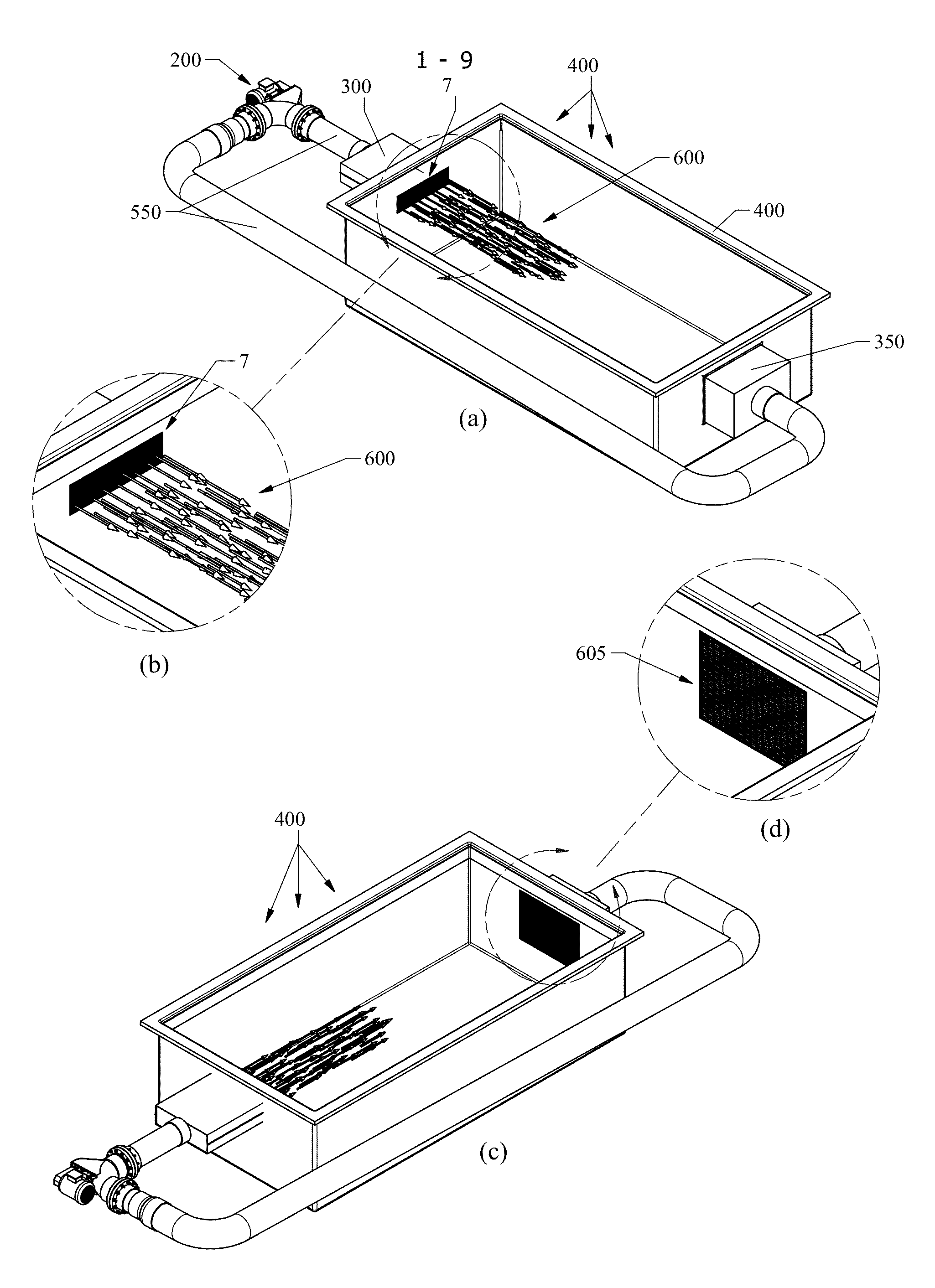
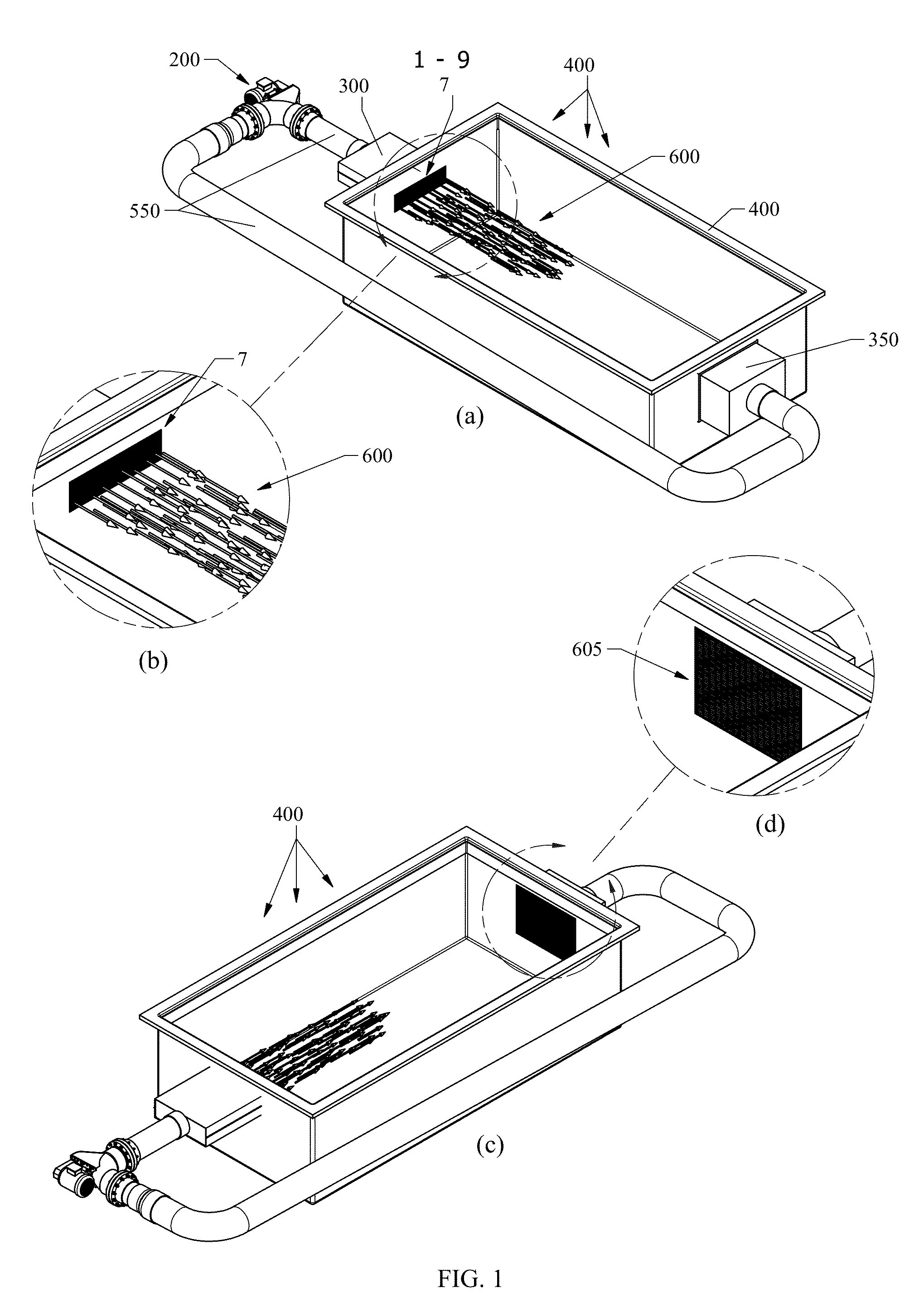
[0034]FIGS. 1a-d show various views and details of the propulsion system 100 in a pool wall mount application according to an embodiment of the present invention. A pool 400 is shown with the laminar flow box assembly 300 attached thereto. An outlet grate 7 of the laminar flow box assembly 300 is shown in the inside of the pool 400. FIG. 1a shows arrows depicting laminar water flow 600 coming from the outlet grate 7 of the laminar flow box assembly 300 toward the suction / return box 350. The suction / return grate 605 is secured to the suction / return box 350 (by fasteners, adhesives or mechanical means). The suction / return grate 605 can be a safety grate that is designed to meet or exceed ASME A112.19.8 2008 standard for unblockable main drain covers as per the requirements for the Virginia Graham Baker Pool and Spa Safety Act ...


PUM


Abstract

The present invention relates generally to propulsion systems, and, more particularly, to a propulsion system including an axial flow water pump assembly and a laminar flow box assembly for generating a streamline laminar slipstream of water velocity that is used in aquatic therapy, aquatic sport fitness rehabilitation, aquatic rehabilitation, swimming, and a variety of other functional therapy and training modalities.

Description

RELATED APPLICATION DATA[0001]The present application claims benefit of U.S. provisional patent application No. 61 / 258,701, filed Nov. 6, 2009, and is hereby incorporated by reference in its entirety.BACKGROUND OF THE INVENTION[0002]1. Field of Invention[0003]The present invention relates generally to propulsion systems, and, more particularly, to a propulsion system including an axial flow water pump assembly and a laminar flow box assembly adapted to generate a variable speed streamline laminar slipstream of water current with a variety of water velocities and thrusts that can be used in aquatic therapy, aquatic sport fitness rehabilitation, aquatic rehabilitation, swimming, sports medicine, and a variety of other functional therapy and training modalities.[0004]2. Description of the Related Art[0005]Propulsion systems with axial flow pumps used in conjunction with swimming pools and the like are conventional. For example, companies such as SwimGym, Inc. (“SwimGym”) and Riverflow ...

Claims


Application Information

Patent Timeline
Patent Type & Authority Patents(United States)
IPC IPC(8): F04D29/52
CPCA63B69/125A61H33/60A61H33/0087F04D29/541F04D3/005F04D29/548
Inventor GILLETTE, PETER, J.
Owner VISION AQUATICS
Why Eureka
Try Eureka