High temperature, high pressure subsea electrical connector system

a high-pressure subsea electrical connector and high-temperature technology, applied in the direction of sealing/packing, coupling device connection, borehole/well accessories, etc., can solve the problem of limited electrical feed-through hole diameter of the tube hanger, the connection or the penetrator cannot be isolated from the pumping pressure, and the extreme environment of the connector or the penetrator. to achieve the effect of improving mechanical strength and better insulation

Active Publication Date: 2014-04-29
TELEDYNE INSTR INC
View PDF14 Cites 23 Cited by
  • Summary
  • Abstract
  • Description
  • Claims
  • Application Information

AI Technical Summary

Benefits of technology

[0010]The corresponding bore portions of the shell which receive the enlarged, load-bearing portions of the pins are of similar or matching non-circular shape and are arranged with the smaller diagonal dimension of each enlarged portion of the bore oriented radially in the shell and opposite projections extending into radial regions of the shell between adjacent bores. In one embodiment, the enlarged or rhomboidal shaped portion of a bore for receiving a first pin has first and second adjacent, non-perpendicular faces which are adjacent and parallel to a corresponding second face of the enlarged portion of a second bore for receiving a second pin and a corresponding first face of the enlarged portion of a third bore for receiving a third feed-through pin, respectively. This permits use of regions within the radial space inside the outer diameter of the shell (which would otherwise be unoccupied if the pins were cylindrical) for load bearing. This arrangement also enables moving of the concentric ceramic ground plane further away than would be possible with an insulation layer of cylindrical shape along its entire length which was concentrically with the conductive shaft. This allows for better insulation along with increased mechanical strength due to the larger load bearing portions of the ceramic insulating layer. The rhomboidal cross-sectional shape of the enlarged portions of the pins passing through the connector allows the packaging of the ceramic insulation within a compact diameter while still providing sufficient insulation to meet the electrical insulation and pressure barrier requirements.

Problems solved by technology

In an ESP application, the connection or penetrator cannot be isolated from the pumping pressure for practical reasons.
This creates an extreme environment for the connector or penetrator in terms of pressure, temperature, and high voltage.
The problem with such feed-through or connector systems is the limited tube hanger (TH) electrical feed-through hole diameter designated for the wet-mate penetrator.
However, the structural integrity as well as the dielectric strength of PEEK can be compromised at higher temperatures.
However, only a limited diameter space is available in the tube hanger for the feed-through system.
This is even more of a problem when more than one feed-through pin is needed.

Method used


Image

  • High temperature, high pressure subsea electrical connector system
  • High temperature, high pressure subsea electrical connector system
  • High temperature, high pressure subsea electrical connector system

Examples


Embodiment Construction

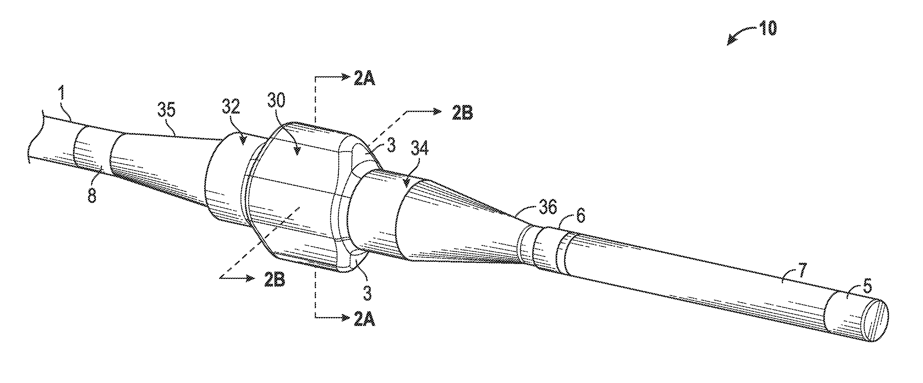
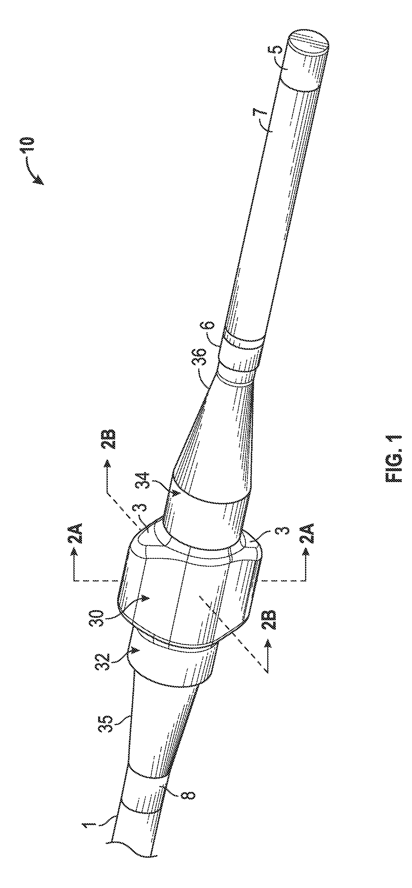
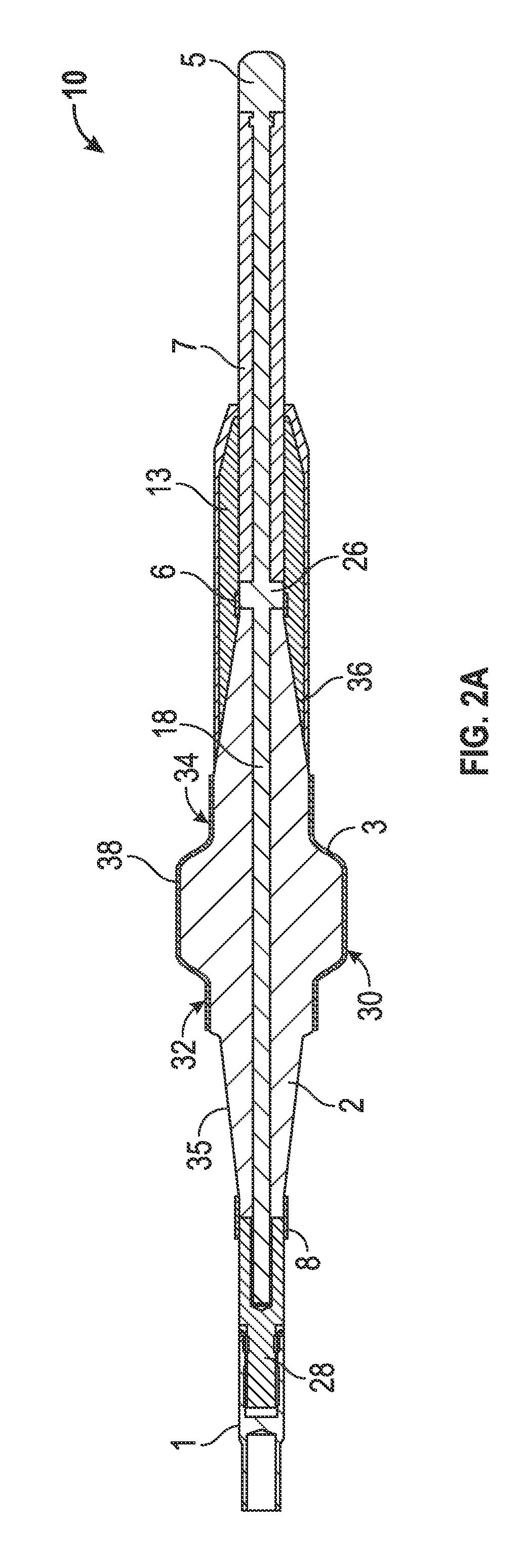
[0025]Certain embodiments as disclosed herein provide for an electrical penetrator assembly suitable for use in high pressure, high temperature and high voltage applications, such as in providing power for subsea equipment such as a down-hole electrical submersible pump (ESP) in an oil well.

[0026]After reading this description it will become apparent to one skilled in the art how to implement the invention in various alternative embodiments and alternative applications. However, although various embodiments of the present invention will be described herein, it is understood that these embodiments are presented by way of example only, and not limitation. As such, this detailed description of various alternative embodiments should not be construed to limit the scope or breadth of the present invention.

[0027]FIGS. 1 to 2B, 4A and 4B illustrate a first embodiment of an electrical penetrator or feed-through pin 10 for a subsea feed-through or wet mate connector, while FIG. 3 illustrates ...


PUM


Abstract

Each feed-through pin of a multiple-phase, high voltage plug-pin connector comprises at least one conductor having a first insulation layer extending along at least part of its length, the insulation layer having an enlarged, load-bearing portion of non-circular cross-section having oppositely directed projections, configured for engagement in a correspondingly shaped bore portion of the connector shell. The load-bearing portions may be of a rhomboidal cross sectional shape with rounded corners, with a first diagonal length shorter than a second diagonal length. The pins are spaced around the central longitudinal axis of the shell with the shorter diagonal of each load-bearing portion extending radially and the oppositely directed projections extending into the radial spaces in the shell between adjacent pins. This arrangement allows space within a limited diameter feed through hole for the enlarged, load-bearing shoulder portions of the insulation layer.

Description

RELATED APPLICATION[0001]The present application claims the benefit of co-pending U.S. provisional pat. App. Ser. No. 61 / 533,351, filed Sep. 12, 2011, the contents of which are incorporated herein by reference in their entirety.BACKGROUND[0002]1. Field of the Invention[0003]The present invention relates generally to an electrical connector assembly or system for subsea use in a high temperature, high pressure, high voltage, and high current environment which may be used as a wet-mate, dry-mate, or feed-through system.[0004]2. Related Art[0005]Electrical connectors or penetrators are used to connect a power source to subsea electric submersible pump (ESP) equipment and the like which pump hydrocarbons in oil well installations, and also in other applications such as high pressure downhole electrical penetrations and other penetrations to provide power to various types of subsea equipment. The penetrator extends through the wall or bulkhead of the vessel in which the equipment is loca...

Claims


Application Information

Patent Timeline
Patent Type & Authority Patents(United States)
IPC IPC(8): H01R13/52
CPCH02G3/22H01R13/523H02G15/14H01R13/53H02G9/02E21B33/0385
Inventor SPAHI, SAMI S.WIDAR, JAMES M.JAZOWSKI, ROY E.
Owner TELEDYNE INSTR INC
Why Eureka
Try Eureka