Magnetic storage apparatus

a magnetic storage and apparatus technology, applied in the field of magnetic storage apparatuses, can solve the problems of reducing the magnetic anisotropy energy, deteriorating the stability of recording signals, and difficult to further increase the recording density by using the system, so as to improve the write-field gradient, improve the response of the magnetic field to the writing current, and reduce the effect of the magnetic field leaked from the auxiliary pol

Active Publication Date: 2014-04-29
WESTERN DIGITAL TECH INC
View PDF16 Cites 0 Cited by
  • Summary
  • Abstract
  • Description
  • Claims
  • Application Information

AI Technical Summary

Benefits of technology

[0043]Further, the same trend as shown in Table 1 was observed also in a case of evaluating the read / write performance by using a head in which a structure including a main pole and an auxiliary pole disposed on the leading side in the down-track direction is provided with a magnetic shield via a non-magnetic gap layer only on the trailing side in the down-track direction of the main pole (refer to FIG. 5(b)) (hereinafter referred to as trailing shield head). Further, same effect as in Table 1 was obtained also in a case of evaluating an identical sample by using a trailing side shield head in which the distance between the main pole and the trailing shield was changed in a range from 50 to 100 nm, or a trailing side shield head in which the shield height was changed in a range from 50 to 250 nm. That is, while the effect of the invention is not observed in the combination with a single-pole-type writer with no shield as shown in Table 2, the same effect as in Table 1 was obtained in a case of using a shielded pole writer even when the dimension of the magnetic head changed.
[0044]Further, the same effect as in Table 1 is obtained also in a case of combination with magnetic heads as shown in FIG. 7A to FIG. 7E in addition to the magnetic head shown in FIG. 2.
[0045]FIG. 7A shows a relation of another combination between a magnetic head 12 and a magnetic recording medium 10 of the invention. A read portion 20 has a read element put between a pair of magnetic shields, and a giant magnetoresistive element (GMR), a tunneling magnetoresistive element (TMR), etc. are used for the read element 21. The recording unit 22 is of a structure including a main pole, two auxiliary poles 25, 25′, and two coils 26, 26′, in which the main pole includes a yoke part of main pole 23′ and a pole tip of main pole 23, and a shield 24 is formed at the periphery of the pole tip of main pole 23 via a non-magnetic gap layer so as to cover at least the trailing side in the down-track direction of the main pole. There are two auxiliary poles and two coils are disposed between them. Current in opposite directions is supplied to the coils 26 and 26′ such that magnetic fluxes flow in the same direction to the main pole. With the structure described above, a magnetic field with improved write-field gradients can be obtained and the rising response of the magnetic field to the writing current can be made fast. Further, since the magnetic field leaked from the auxiliary pole can be decreased, erasing of data written on the medium can be prevented.
[0046]FIG. 7B shows a relation of another combination between a magnetic head 12 and a magnetic recording medium 10 according to embodiments of the invention. A read portion 20 has a read element put between a pair of magnetic shields, and a giant magnetoresistive element (GMR), a tunneling magnetoresistive element (TMR), etc. are used for the read element 21. The recording unit 22 is of a structure including a main pole, two auxiliary poles 25, 25′, and coils 26, in which the main pole includes a yoke part of main pole 23′ and a pole tip of main pole 23, and a shield 24 is formed at the periphery of the pole tip of main pole 23 via a non-magnetic gap layer so as to cover at least the trailing side in the down-track direction of the main pole. This is a structure in which the coil 26 is wound around the main pole. Also with the structure described above, a magnetic field with improved write-field gradients can be obtained and the rising response of the magnetic field to the writing current can be made fast. Further, since the magnetic field leaked from the auxiliary pole can be decreased, erasing of data written on the medium can be prevented.
[0047]FIG. 7C shows a relation of another combination between a magnetic head 12 and a magnetic recording medium 10 according to embodiments of the present invention. A read portion 20 has a read element put between a pair of magnetic shields, and a giant magnetoresistive element (GMR), a tunneling magnetoresistive element (TMR), etc. are used for the read element 21. The recording unit 22 is of a structure including a main pole, an auxiliary pole 25, and two coils 26, 26′, in which the main pole includes a yoke part of main pole 23′ and a pole tip of main pole 23, and a shield 24 is formed at the periphery of the pole tip of main pole 23 via a non-magnetic gap layer so as to cover at least the trailing side in the down-track direction of the main pole. Coils are disposed on both of the trailing side and the leading side of the main pole. Current in opposite directions is supplied to the coils 26, 26′ such that magnetic fluxes in the same direction flow to the main pole. Further, an auxiliary shield 27 made of magnetics is disposed between the main pole and the read shield so as to prevent the magnetic flux from flowing into the read element from the main pole. With such structure described above, the magnetic head improved with the write-field gradients can be obtained, and the rising response of the magnetic field to the writing current can be made fast while suppressing the flowing of the magnetic flux into the read element. Further, since the magnetic field leaking from the auxiliary pole can be decreased, erasing of data written on the medium can be prevented.
[0048]FIG. 7D shows a relation of another combination between a magnetic head 12 and a magnetic recording medium 10 according to an embodiments of the present invention. A read portion 20 has a read element put between a pair of magnetic shields, and a giant magnetoresistive element (GMR), a tunneling magnetoresistive element (TMR), etc. are used for the read element 21. The recording unit 22 is of a structure including a main pole, an auxiliary pole 25, and two coils 26, 26′, in which the main pole includes a yoke part of main pole 23′ and a pole tip of main pole 23, and a shield 24 is formed at the periphery of the pole tip of main pole 23 via a non-magnetic gap layer so as to cover at least the trailing side in the down-track direction of the main pole. It has a feature in that the coils are disposed on both of the trailing side and the leading side of the main pole. Current in opposite directions is supplied to the coils 26, 26′ such that magnetic fluxes in the same direction flow to the main pole. With such a structure, a magnetic field improved with the write-field gradients can be obtained and the rising response of the magnetic field to the write current can be made fast. Further, since the magnetic field leaking from the auxiliary pole can be decreased, erasing of data written on the medium can be prevented.

Problems solved by technology

While a hard disk unit using a longitudinal magnetic recording system has attained an in-plane recording density exceeding 20 Gbits / cm2, it has become difficult to further increase the recording density by using the system.
In this case, it results in a problem of lowering the magnetic anisotropy energy and deteriorating the stability of recording signals.
However, while the medium described above has large Ku and excellent thermal stability, it causes deterioration of the overwrite characteristic (hereinafter referred to as OW characteristic) since the coercivity of the medium increases.
In addition, as the track becomes narrower, a problem occurs when the effective track width to be written into a medium is larger than the geometrical track width, which forms a bottleneck for the improvement of the track density.
However, since the write-field intensity is small, no sufficient OW characteristic can be obtained easily.
As described above, while a perpendicular magnetic recording medium in which a recording layer comprising a CoCr alloy not containing oxide is stacked on a granular type recording layer with addition of an oxide to a CoCrPt alloy is excellent in the OW characteristic, the condition for obtaining a sufficient OW characteristic is still severe even in the case of using such a medium when it is in combination with the shielded pole writer and the medium SNR is inevitably degraded.
That is, it has been extremely difficult to attain a recording density exceeding 30 Gbits / cm2 by overcoming a trade off relation between the OW characteristic and the medium SNR.

Method used


Image

  • Magnetic storage apparatus
  • Magnetic storage apparatus
  • Magnetic storage apparatus

Examples


experimental example 1

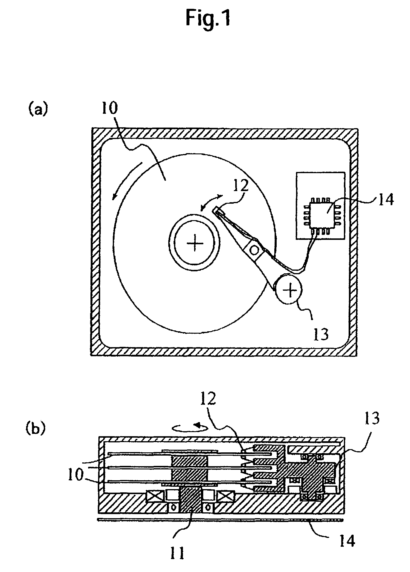
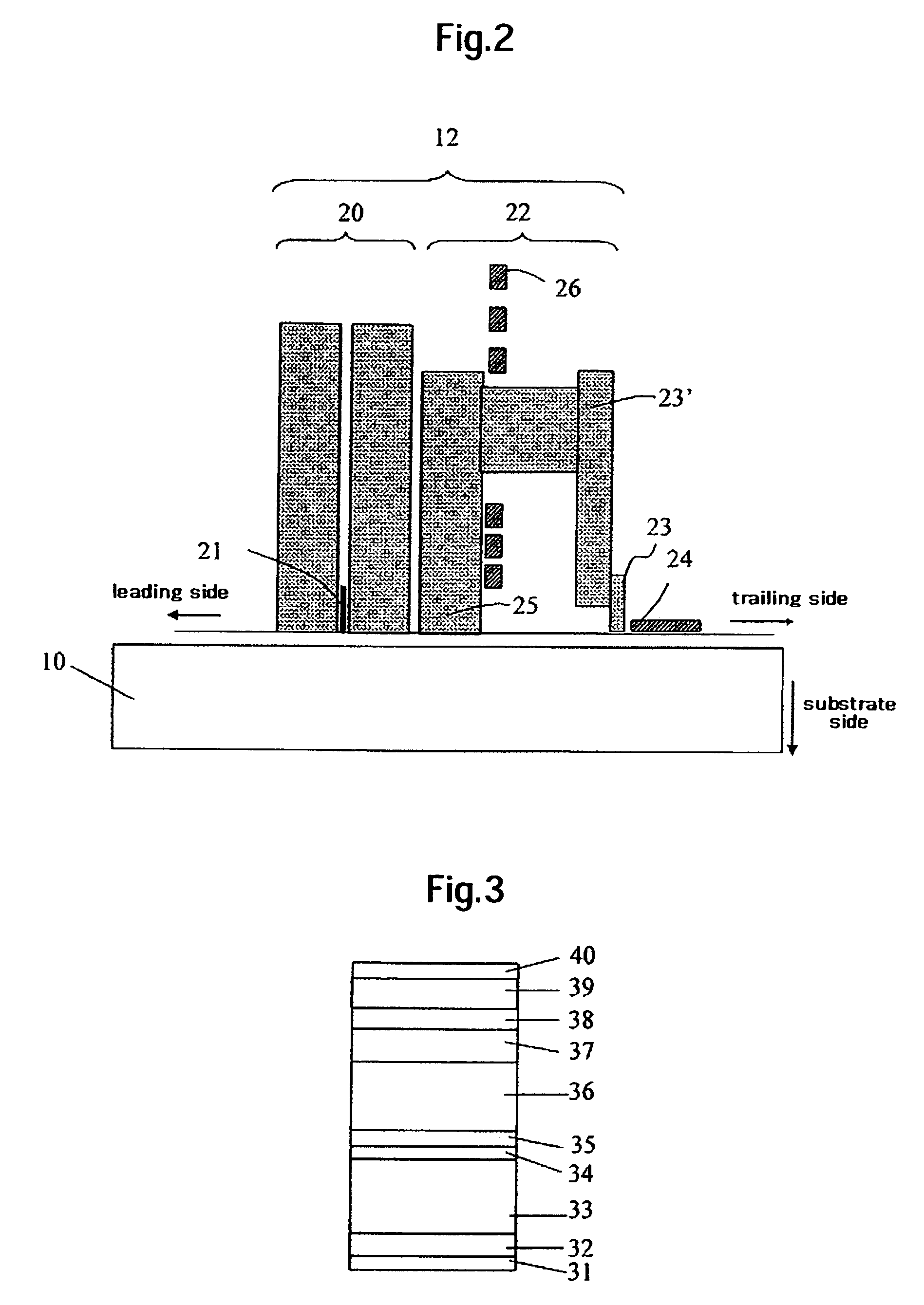
[0029]FIG. 1 shows a schematic view of a magnetic storage apparatus as an example of one embodiment of the present invention. FIG. 1(a) is a schematic plan view and FIG. 1(b) is a schematic cross sectional view thereof. The magnetic storage apparatus includes a magnetic recording medium 10, a driving section 11 for driving the magnetic recording medium, a magnetic head 12 comprising a recording unit and a read portion, means 13 for relatively moving the magnetic head to the magnetic recording medium, and means 14 for inputting and outputting signals to the magnetic head. A relation between the magnetic head 12 and the magnetic recording medium 10 is shown in FIG. 2. The read section 20 has a read element put between a pair of magnetic shields, and a giant magnetoresistive (GMR) element, or tunneling magnetoresistive (TMR) element, etc. is used for the read element 21. The recording unit 22 is of a structure having a main pole, an auxiliary pole 25, and a coil 26, in which the main p...

experimental example 2

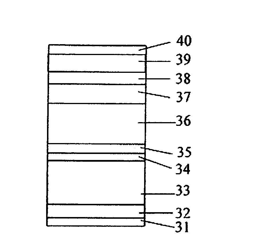
[0052]A perpendicular magnetic recording medium of Experimental Example 2 was manufactured by the same film structure and the same film forming conditions as those for Sample 1-8 in Experimental Example 1 except for the second recording layer and the third recording layer. In Experimental Example 2, the composition and the film thickness of the second recording layer and the third recording layer were changed. The read / write performance was evaluated by using the same trailing side shield head as in the case of Table 1 for Experimental Example 1. Table 3 shows the composition and the film thickness of the second recording layer and the third recording layer, and the result of the read / write performance. Table 3 also shows the value of t2 / (t2+t3) in a case wherein the thickness of the second recording layer is represented by t2 (nm) and the thickness of the third recording layer is represented by t3 (nm).

[0053]

TABLE 3SecondThirdRead / writerecording layerrecording layerperformanceFilmF...

experimental example 3

[0058]Samples of Experimental Example 3 were manufactured by the same film structure and the same film forming conditions as those for Sample 1-8 in Experimental Example 1 except for the second recording layer and the third recording layer. The thickness of the second recording layer was 2 nm, the thickness of the third recording layer was 6 nm (t2 / (t2+t3)=0.25), the Pt concentration for each of the second recording layer, and the third recording layer was set to 11 at. % and the Cr concentration and the Co concentration were changed. For the samples, the medium SNR was evaluated by using the same trailing side shield head as in the case of Table 1 of Experimental Example 1. The difference between the Cr concentration (a) in the second recording layer and the Cr concentration (b) in the third recording layer (b−a) was determined and the obtained medium SNR is shown in Table 4. In Table 4, samples showing the medium SNR higher by 2 dB than that of Sample 1-4 in Table 1 (22.4 dB or mo...


PUM

PropertyMeasurementUnit
widthaaaaaaaaaa
lengthaaaaaaaaaa
acceleration voltageaaaaaaaaaa

Abstract

According to embodiments of the present invention, a shielded pole writer and a perpendicular magnetic recording medium suitable thereto are combined to provide high medium SNR and excellent OW characteristic simultaneously. A perpendicular magnetic recording medium of a magnetic storage apparatus mounting a shielded pole writer, including a perpendicular magnetic recording medium having a recording layer of a three layered structure is used. A first recording layer has a granular structure consisting of grain boundaries containing an oxide and columnar grains comprising a CoCrPt alloy, in which a second recording layer and a third recording layer formed thereabove comprise Co as a main ingredient, contain Cr and do not contain an oxide, and the Cr concentration in the second recording layer is lower than the Cr concentration in the third recording layer.

Description

CROSS-REFERENCE TO RELATED APPLICATION[0001]The instant nonprovisional patent application claims priority to Japanese Patent Application No. 2006-081044 filed Mar. 23, 2006 and incorporated by reference in its entirety herein for all purposes.BACKGROUND OF THE INVENTION[0002]In recent years, the amount of information handled by computers has been increased and consequently an increase in the capacity of a hard disk unit as an auxiliary memory apparatus has been demanded. Further, along with progress for the mounting of a hard disk unit to domestic electric products, demand for decreasing the size and increasing the capacity of the hard disk unit has been increased more and more. While a hard disk unit using a longitudinal magnetic recording system has attained an in-plane recording density exceeding 20 Gbits / cm2, it has become difficult to further increase the recording density by using the system. As an alternative system, a perpendicular recording system has now been investigated....

Claims


Application Information

Patent Timeline
Patent Type & Authority Patents(United States)
IPC IPC(8): G11B5/66
CPCG11B5/66G11B5/11G11B5/3146G11B5/3967G11B5/315G11B5/3116G11B5/656G11B5/1278G11B5/672
Inventor TAKEKUMA, IKUKONAKAGAWA, HIROYUKINEMOTO, HIROAKIHIRAYAMA, YOSHIYUKI
Owner WESTERN DIGITAL TECH INC
Why Eureka
Try Eureka