
Amplitude-shift-keying (ASK) envelope detector and demodulation circuits
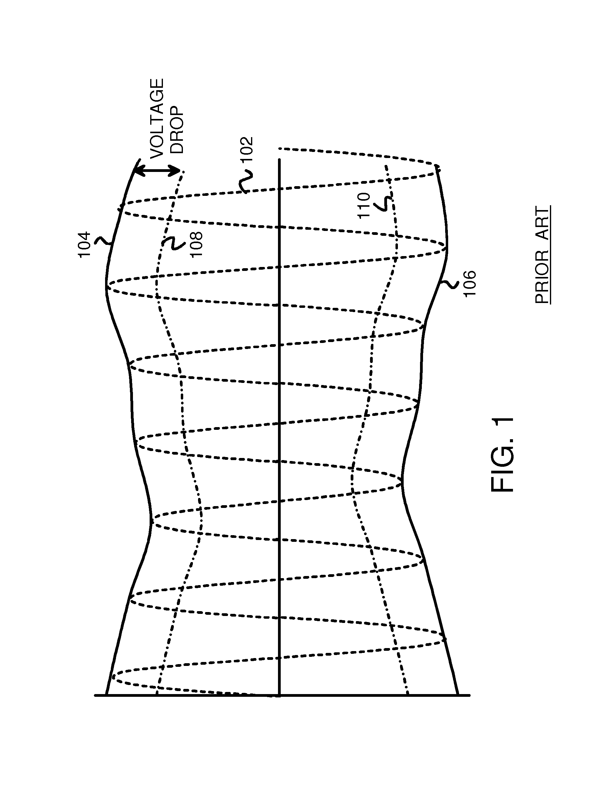
a demodulator circuit and envelope detector technology, applied in the direction of amplitude demodulation, amplitude demodulation by homodyne/synchrodyne circuit, electrical apparatus, etc., can solve the problem that the stability of some envelope detectors may not be affected, the schmidt-trigger stage may not operate over a wide range of input voltage or signals, and the circuit losses of real envelope detectors may produce voltage drops or losses
- Summary
- Abstract
- Description
- Claims
- Application Information
AI Technical Summary
Benefits of technology
Problems solved by technology
Method used
Image

Examples
Embodiment Construction
[0021]The present invention relates to an improvement in envelope detectors. The following description is presented to enable one of ordinary skill in the art to make and use the invention as provided in the context of a particular application and its requirements. Various modifications to the preferred embodiment will be apparent to those with skill in the art, and the general principles defined herein may be applied to other embodiments. Therefore, the present invention is not intended to be limited to the particular embodiments shown and described, but is to be accorded the widest scope consistent with the principles and novel features herein disclosed.
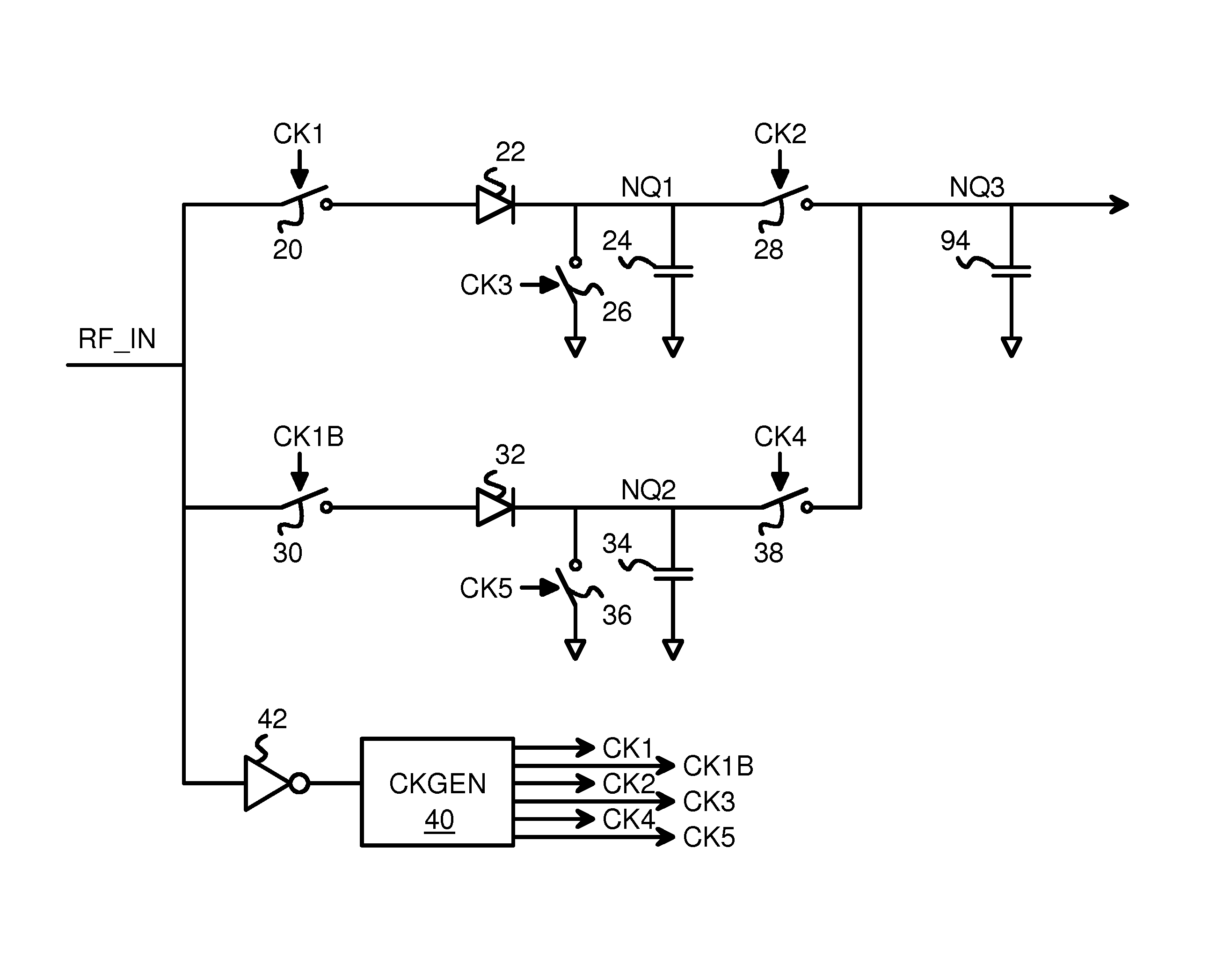
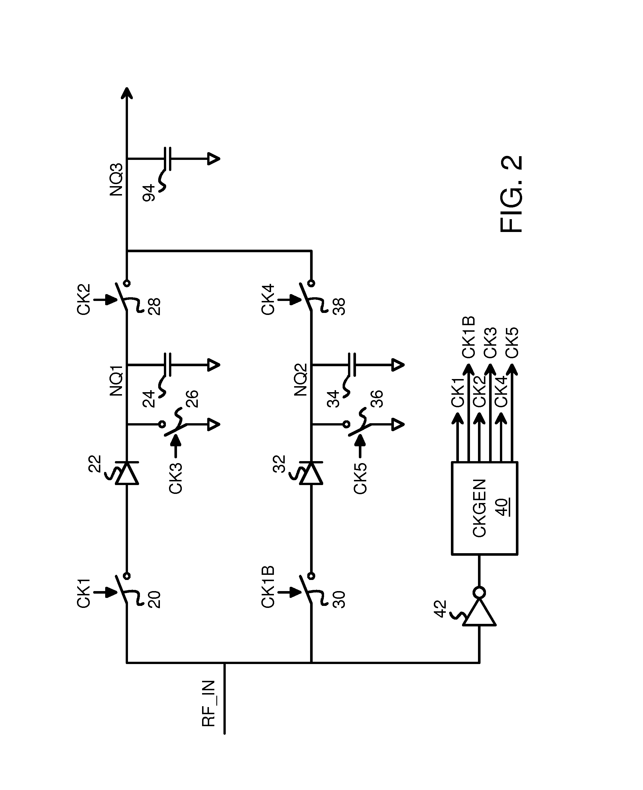
[0022]FIG. 2 is a diagram of a dual-channel sample and hold envelope detector. A received signal RF_IN is applied to clock-recovery inverter 42 and clock generator 40 to generate clocks CK1, CK1B, CK2 . . . CK5. The timing of these generated clocks is shown in FIG. 4. RF_IN is an Amplitude-Modulated (AM) or Amplitude-Shift-Keying (...
PUM
 Abstract
Description
Claims
Application Information