System for hydrogen charging

a hydrogen charging and hydrogen technology, applied in the direction of container filling under pressure, vessel construction details, transportation and packaging, etc., can solve the problems of non-uniform gas charging efficiency and inability to carry out efficient charging, and achieve the effect of increasing channel resistance, larger heat flux, and small siz

Active Publication Date: 2014-05-06
TOYOTA JIDOSHA KK
View PDF17 Cites 4 Cited by
  • Summary
  • Abstract
  • Description
  • Claims
  • Application Information

AI Technical Summary

Benefits of technology

[0010]An advantage of the present invention is to provide a system for charging hydrogen capable of uniform charging between a plurality of hydrogen tanks. Another advantage of the present invention is to provide a system for hydrogen charging capable of having a plurality of hydrogen tanks all in the fully charged state. The means described below contribute to achieving at least one of these advantages.
[0011]A system for hydrogen charging according to the present invention comprises supply channels for connecting a hydrogen charging device and respective hydrogen tanks; and a flow restrictor for increasing a channel resistance of the supply channel connected to the hydrogen tank having larger heat flux to be larger than a channel resistance of the supply channel connected to the hydrogen tank having smaller heat flux or increasing a pressure loss of the supply channel connected to the hydrogen tank having larger heat flux to be larger than a pressure loss of the supply channel connected to the hydrogen tank having smaller heat flux.
[0012]In the system for hydrogen charging according to the present invention, preferably, the flow restrictor may be an orifice restrictor provided to the supply channel connected to the hydrogen tank having larger heat flux.
[0013]In the system for hydrogen charging according to the present invention, preferably, the flow restrictor may comprise check valves provided to the respective supply channels, and a cracking pressure of the check valve provided to the supply channel connected to the hydrogen tank having larger heat flux may be higher than a cracking pressure of the check valve provided to the supply channel connected to the hydrogen tank having smaller heat flux.
[0014]In the system for hydrogen charging according to the present invention, preferably, the plurality of hydrogen tanks may be fuel gas tanks mounted on a vehicle, and the hydrogen tank having larger heat flux may be a tank having a larger surface area per unit volume, a tank made of material having a larger heat conductive rate, or a tank mounted on a vehicle at a position more advantageous in ensuring larger heat flux, compared to the hydrogen tank having smaller heat flux.Advantage of the Invention
[0015]With the above described structure, the system for hydrogen charging has a flow restrictor for increasing the channel resistance of the supply channel connected to the hydrogen tank having larger heat flux so as to be larger than that of the hydrogen tank having smaller heat flux or increasing a pressure loss of the supply channel connected to the hydrogen tank having larger heat flux so as to be larger than that of the hydrogen tank having smaller heat flux.

Problems solved by technology

Thus, when the hydrogen gas in the hydrogen tank runs short, the vehicle needs to stop at a hydrogen supply station or the like to charge the hydrogen tank with hydrogen gas.
Patent Document 2 points out that, although mounting a plurality of tanks having different heat discharge characteristics on a vehicle is more efficient than mounting a single tank, in that respective characteristics can be utilized, it is not possible to carry out efficient charging when charging of the respective tanks begins at the same time, as the gas temperatures of the respective tanks increase by different amounts, and consequently, the tanks are non-uniform in gas charging efficiency.

Method used


Image

  • System for hydrogen charging
  • System for hydrogen charging
  • System for hydrogen charging

Examples


Embodiment Construction

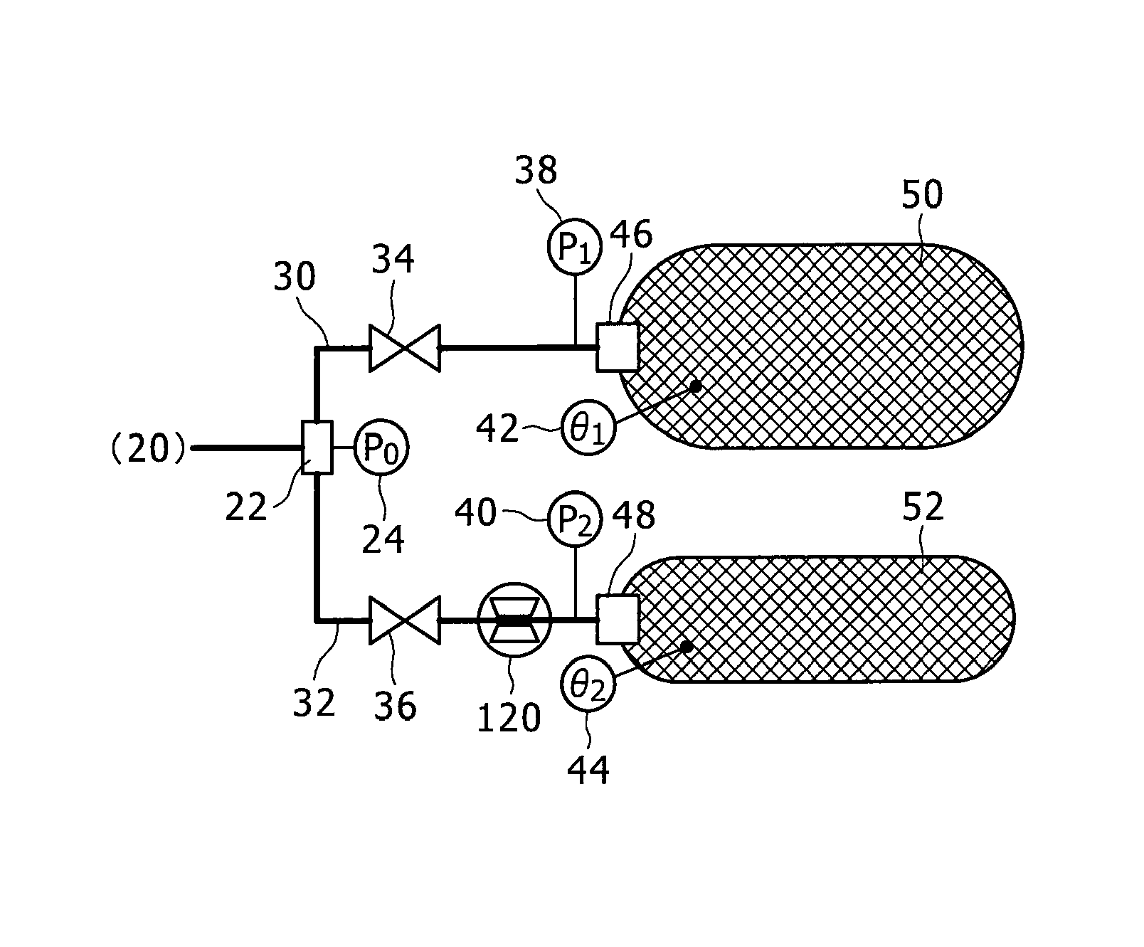
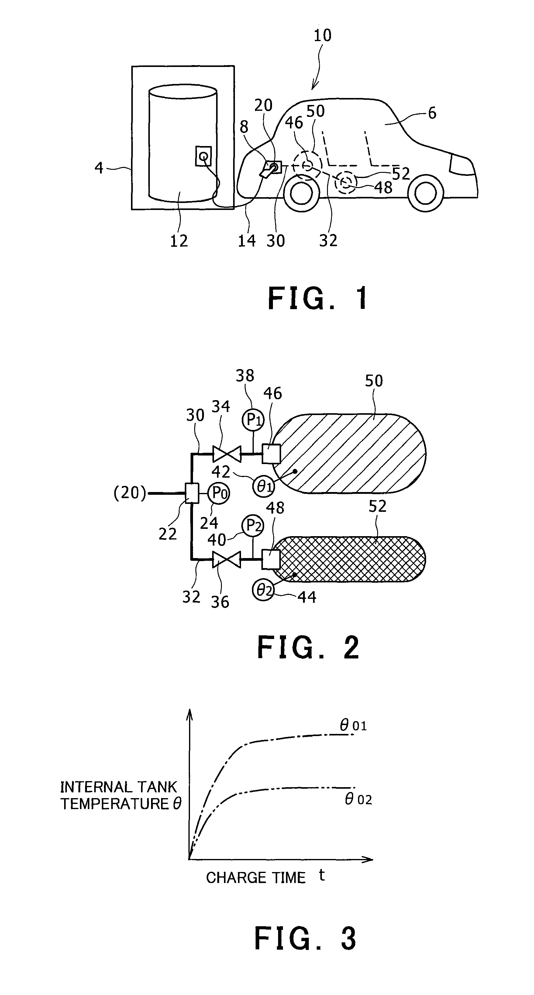
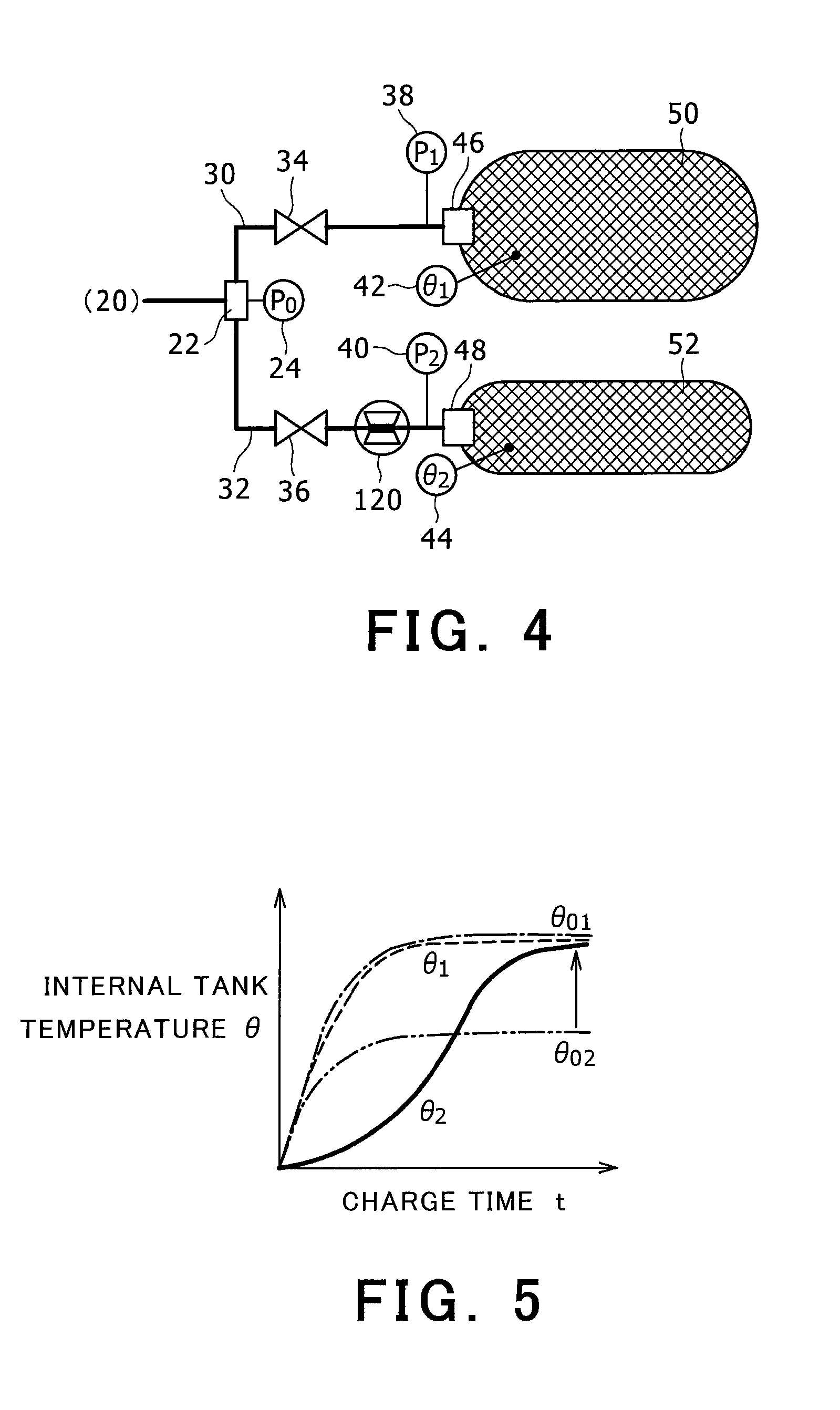
[0031]In the following, an embodiment of the present invention will be described by reference to the drawings. In the following, a case of charging two hydrogen tanks having different shapes mounted on an electric vehicle with hydrogen gas will be described as a system for hydrogen charging. However, the present invention also encompasses a case in which a plurality of hydrogen tanks, including one not mounted on an electric vehicle, are charged with hydrogen gas from a hydrogen charging device. For example, a case including a plurality of fuel tanks of an installation type fuel cell is included. The number of hydrogen tanks may be three or more. The plurality of hydrogen tanks are not limited to those having different shapes, and any hydrogen tanks having different heat fluxes are applicable. A case in which the difference in the heat flux is attributed to amount or placement position of each hydrogen tank is also included.

[0032]Note that the temperature, pressure, and the like men...


PUM


Abstract

A system for hydrogen charging has an orifice provided as a flow restrictor between a hydrogen charging port and a hydrogen tank having a larger heat flux value. No orifice is provided on the side of a hydrogen tank having a smaller heat flux value. The orifice has a function of increasing the channel resistance. With the above, it is possible to initially have the hydrogen tank having a smaller heat flux value in the fully charged state, and thereafter the hydrogen tank having a larger heat flux value in the fully charged state. Alternatively, a check valve having a cracking pressure ΔP2 can be provided as a flow restrictor on the side of the hydrogen tank having larger heat flux, and a check valve having a cracking pressure ΔP1 can be provided as a flow restrictor on the side of the hydrogen tank having smaller heat flux, wherein ΔP2>ΔP1.

Description

[0001]This is a 371 national phase application of PCT / JP2010 / 057758 filed 6 May 2010, the contents of which are incorporated herein by reference.TECHNICAL FIELD[0002]The present invention relates to a system for hydrogen charging, and in particular to a system for hydrogen charging for charging a plurality of hydrogen tanks with hydrogen gas from a hydrogen charging device.BACKGROUND ART[0003]A vehicle having a fuel cell that uses hydrogen gas as fuel gas causes a fuel tank to be charged with hydrogen gas, and runs while consuming the hydrogen gas. Thus, when the hydrogen gas in the hydrogen tank runs short, the vehicle needs to stop at a hydrogen supply station or the like to charge the hydrogen tank with hydrogen gas.[0004]For example, Patent Document 1 describes that, as a hydrogen supply station, supply from a hydrogen supply tank is controlled based on the maximum working pressure of a vehicle-mounted hydrogen tank to be supplied hydrogen gas, using a tank specification determi...

Claims


Application Information

Patent Timeline
Patent Type & Authority Patents(United States)
IPC IPC(8): F17D1/00
CPCF17C5/06F17C2201/056F17C2270/0178F17C2201/0109F17C2201/054B60K15/04F17C2270/0168Y02E60/34F17C5/007F17C2221/012F17C2205/0335B60K15/07F17C2250/043F17C2205/013Y02E60/321F17C2250/0636Y10T137/469Y10T137/4857Y02E60/32
Inventor MORI, DAIGOROKOMIYA, KENJINISHIZAWA, KUMIKO
Owner TOYOTA JIDOSHA KK
Why Eureka
Try Eureka