Pedestrian protection apparatus for vehicle

a technology for protecting equipment and vehicles, applied in bumpers, roofs, tractors, etc., can solve the problems of deteriorating aerodynamic performance at the lower region of the vehicle, difficult to guide the airflow to the rear side, etc., to achieve stably secured, reduce the aerodynamic drag of the front section, and improve the deformation strength against the load from the front side to the rear side of the vehicle.

Active Publication Date: 2014-05-06
KOJIMA PRESS IND CO LTD
View PDF41 Cites 6 Cited by
  • Summary
  • Abstract
  • Description
  • Claims
  • Application Information

AI Technical Summary

Benefits of technology

[0014]The present invention was made in the light of the above-described situations. It is therefore an object of the present invention to provide an improved structure of a pedestrian protection apparatus that is not only capable of sufficiently and surely protecting a pedestrian, but also capable of effectively improving the aerodynamic performance at the lower region of the vehicle by reducing aerodynamic drag to the maximum extent possible.
[0027]In the pedestrian protection apparatus for a vehicle according to the present invention, there is provided at a front section thereof a reinforcing portion constituted by a plurality of cylindrical structures that extend in the front to back direction. As a result, at the front section, the deformation strength against the load from the front side to the rear side of the vehicle is sufficiently improved.
[0028]Further, the vertical ribs and the upper and lower connecting plates, which constitute the reinforcing portion, are arranged so as to extend in the front to back direction of the vehicle. In addition, the vertical ribs are opposed to each other in the vehicle width direction and the upper connecting plate and the lower connecting plate are opposed to each other in the vertical direction. Due to this arrangement, unlike the conventional apparatus that includes the horizontal ribs and the connecting ribs that extend in the vehicle width direction with the surfaces thereof facing in the front to back direction, the pedestrian protection apparatus of the present invention does not include any members or portions that contact and block an airflow at the front section including the reinforcing portion. Thus, the aerodynamic drag of the front section is sufficiently made small and smooth airflow to the rear side can be stably secured.
[0029]Due to installation of the pedestrian protection apparatus of the present invention at the lower region of the front of the vehicle, pedestrians can sufficiently and surely be protected, and the lower region of the vehicle can have improved aerodynamic performance, compared with the conventional apparatus.

Problems solved by technology

However, various studies conducted by the present inventors revealed that the structure of the above-described conventional pedestrian protection apparatus has the following problem.
In other words, in the conventional pedestrian protection apparatus, the horizontal ribs and the connection ribs function as aerodynamic drag (air resistance), which make it difficult to guide the airflow to the rear side.
Thus, the conventional pedestrian protection apparatus can surely protect the pedestrian by being provided at the lower region of the vehicle, but may deteriorate the aerodynamic performance at the lower region of the vehicle.

Method used


Image

  • Pedestrian protection apparatus for vehicle
  • Pedestrian protection apparatus for vehicle
  • Pedestrian protection apparatus for vehicle

Examples


first embodiment

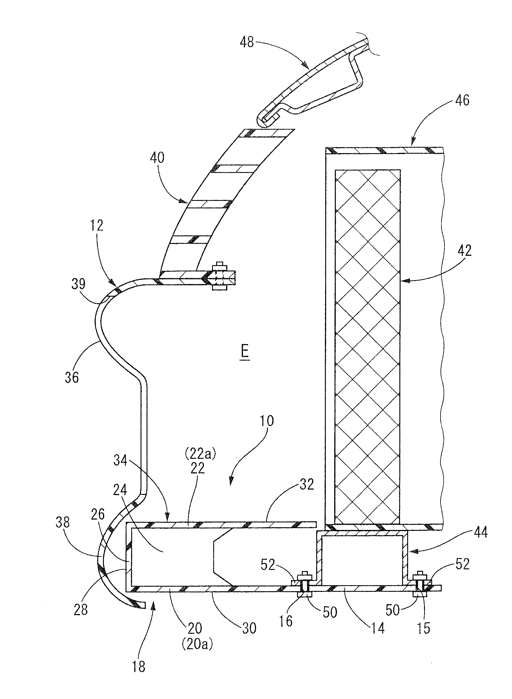
[0087]At the front end of the upper surface of the lower connecting plate 20, the front wall 26 is integrally vertically provided. The front wall 26 has the same structure as the front wall 26 of the leg-sweep apparatus 10 of the first embodiment, which is integrally provided at the lower connecting plate 20.

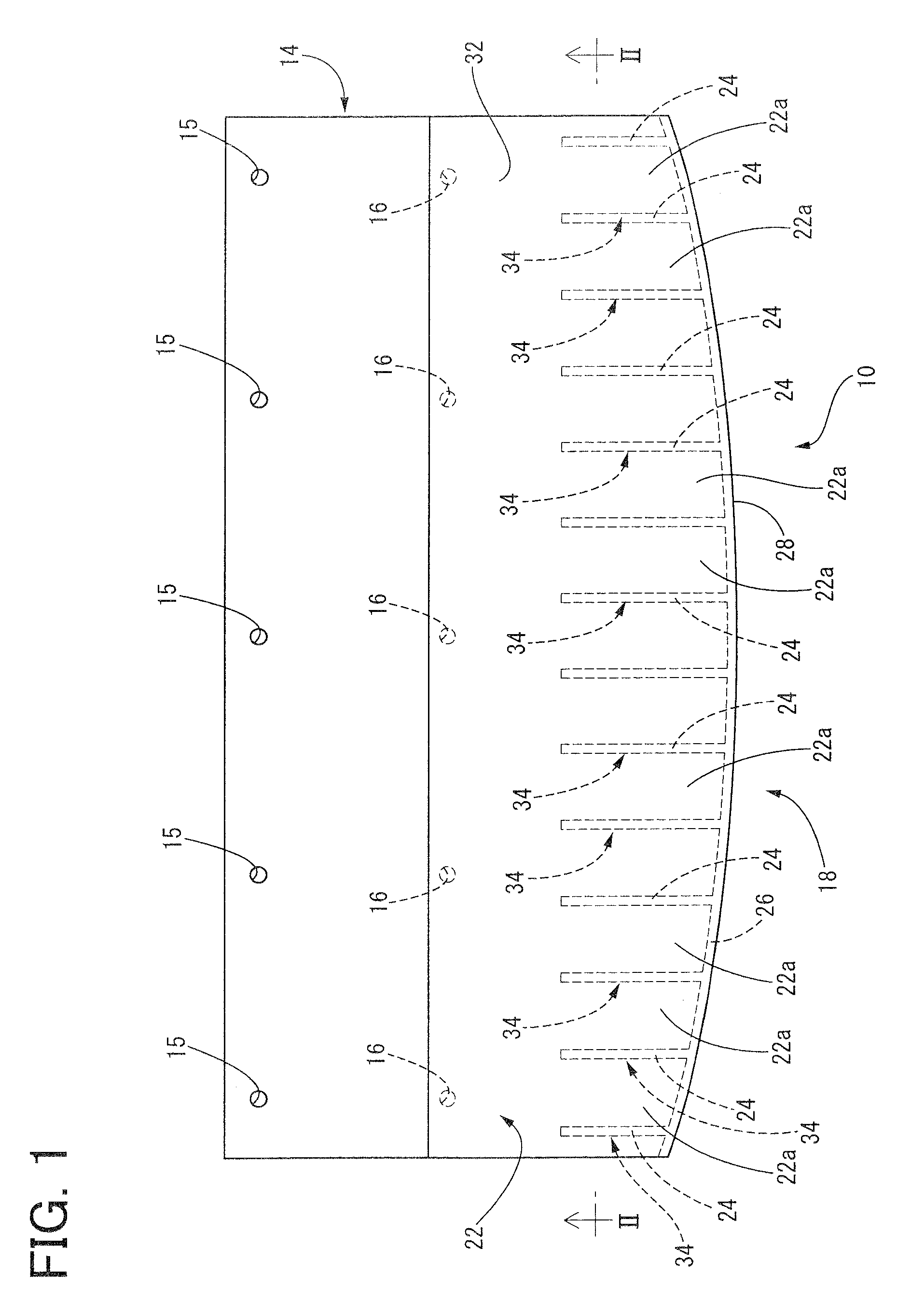
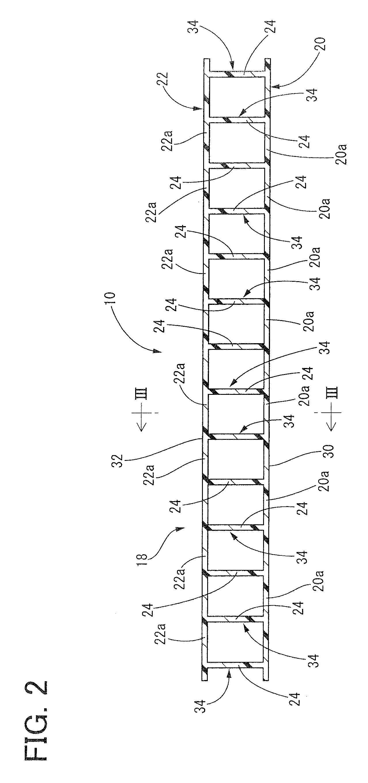
[0088]The vertical ribs 24 are each made of a rectangular plate having the same thickness as the attachment plate 14 and the lower connecting plate 20, the smaller dimension in the front to back direction than the lower connecting plate 20, and the same height as the front wall 26. The vertical ribs 24 are positioned at left and right ends of the first reinforcing bead 56 in the front section of the horizontal plate 60 so as to extend straight rearwardly to the middle in the front to back direction from the front end of the lower connecting plate 20 while being opposed to each other. The vertical ribs 24 are integrally provided on the lower connecting plate 20.

[0089]In other wor...

third embodiment

[0114]With reference to a third embodiment shown in FIG. 10, the dimension in the front to back direction of the vertical rib 24 may be substantially the same as that of the upper connecting plate 22. In such a case, the upper connecting plate 22 and the lower connecting plate 20 can be connected by the vertical rib 24 extending across the entire length of the plates in the front to back direction. This may effectively improve the rigidity of the reinforcing portion 18.

fourth embodiment

[0115]With reference to a fourth embodiment shown in FIG. 11, the dimension in the front to back direction of the vertical rib 24 may be smaller than that of the lower connecting plate 20, and the dimension in the front to back direction of the upper connecting plate 22 may be substantially the same as that of the vertical rib 24. In such a case, the rigidity of the reinforcing portion 18 can be sufficiently secured, and the material cost may be advantageously reduced.

[0116]With reference to a fifth embodiment shown in FIG. 12, the dimension in the front to back direction of the vertical rib 24 may be larger than that of the upper connecting plate 22. In such a case, it is preferable that the vertical ribs 24 has such a dimension in the front to back direction as to contact with the front face of the radiator support 44 at the rear end of the vertical rib 24, under installation of the leg-sweep apparatus 10 at the lower region of the front of the vehicle. That is, unlike the first a...


PUM


Abstract

A pedestrian protection apparatus for a vehicle is provided that can sufficiently protect a pedestrian and can advantageously improve aerodynamic performance at a lower region of the vehicle. The apparatus includes a reinforcing portion at a front section thereof. The reinforcing portion includes a plurality of cylindrical structures that extend in a front to back direction of the vehicle and are arranged in a line in a vehicle width direction. The cylindrical structures include: vertical ribs that are opposed to each other in the vehicle width direction and extend in the front to back direction of the vehicle; an upper connecting plate that extends across upper ends of all of the vertical ribs so as to integrally connect the upper ends; and a lower connecting plate that extends across lower ends of all of the vertical ribs so as to integrally connect the lower ends.

Description

[0001]The present application is based on Japanese Patent Application No. 2011-153062 filed on Jul. 11, 2011, the contents of which are incorporated herein by reference.BACKGROUND OF THE INVENTION[0002]1. Field of the Invention[0003]The present invention relates to a pedestrian protection apparatus for a vehicle, and in particular to an improved structure of the pedestrian protection apparatus disposed at a lower region of a front of the vehicle and arranged to apply a counterforce to a leg portion of a pedestrian by contact with the leg portion of the pedestrian that has collided or contacted with a front face of the vehicle, thereby protecting the leg portion of the pedestrian.[0004]2. Description of the Related Art[0005]In vehicles such as automobiles, there are conventionally disposed, at a front face, a rear face, or side faces, of the vehicles, various types of protection apparatus which absorb an impact energy generated upon a collision, for thereby protecting the vehicle bod...

Claims


Application Information

Patent Timeline
Patent Type & Authority Patents(United States)
IPC IPC(8): B60R19/18B60R21/34
CPCB60R19/18B60R2019/1866B60R2019/1846B60R2021/0053
Inventor HASEGAWA, KUNIAKINOYORI, KEISUKE
Owner KOJIMA PRESS IND CO LTD
Why Eureka
Try Eureka