Visible and infrared light source for illumination system and projection device comprising the same

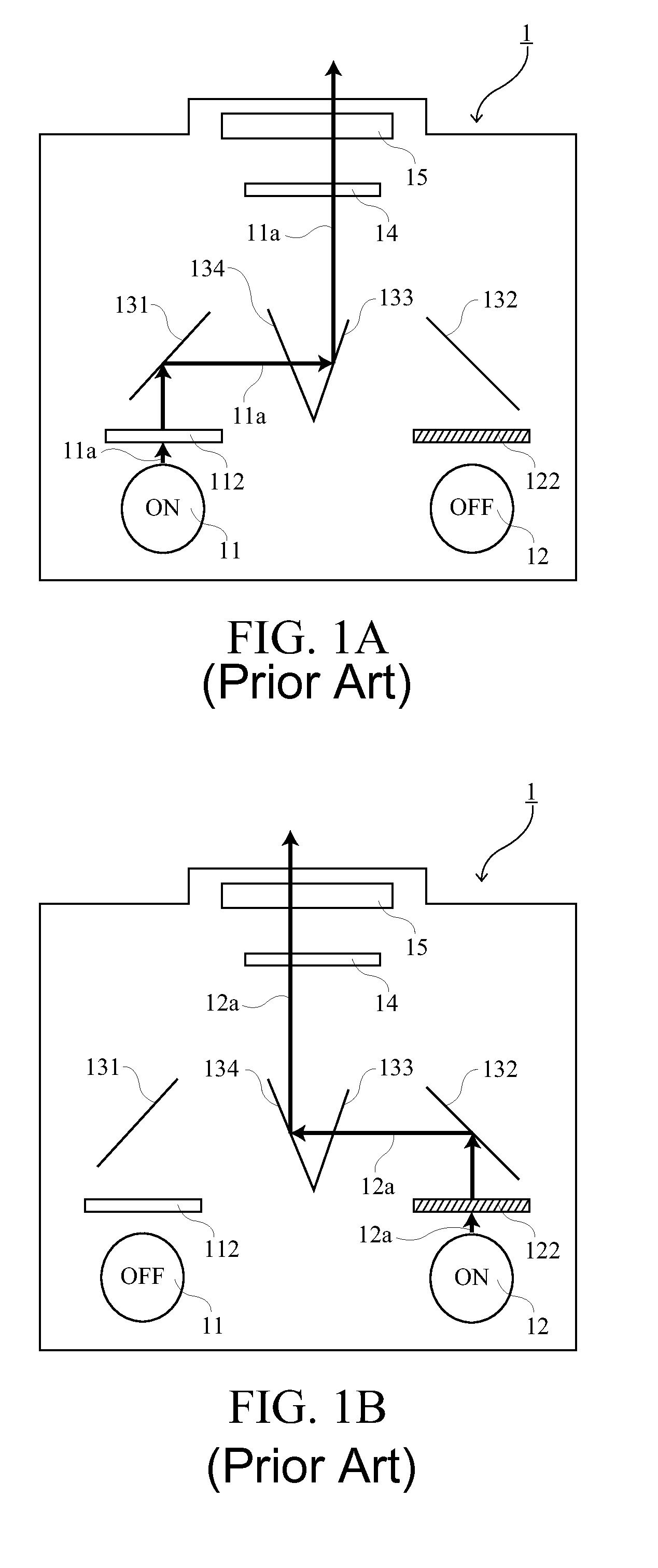
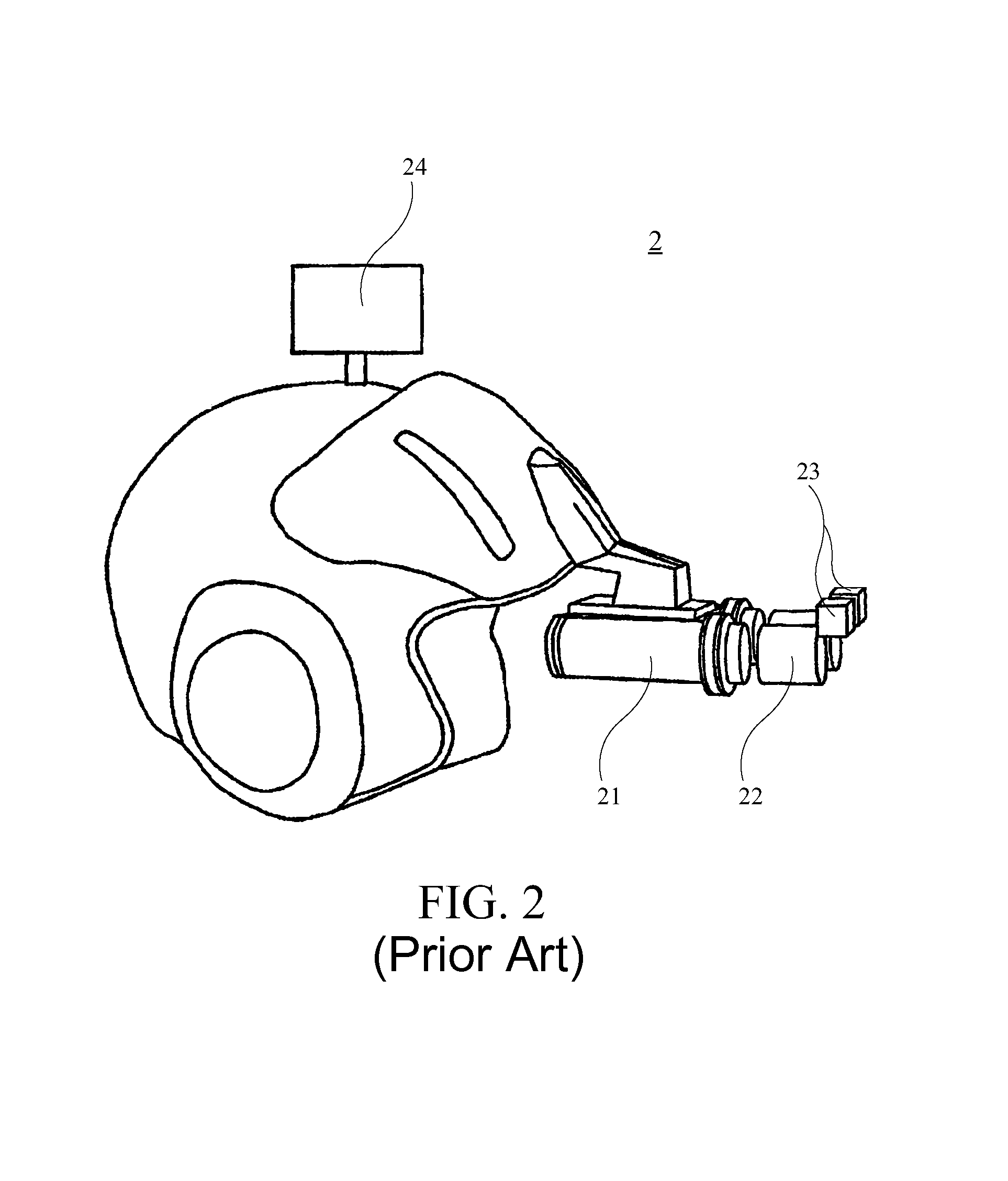
a projection device and infrared light source technology, applied in the field of illumination system for projection device, can solve the problems of generating a great deal of heat energy, human eyes cannot see objects in such environments, and the usual use of night vision projector b>1/b>, and achieves low heat energy generation, high luminance, and high light utilization efficiency.

Active Publication Date: 2014-05-06
DELTA ELECTRONICS INC
View PDF29 Cites 2 Cited by
  • Summary
  • Abstract
  • Description
  • Claims
  • Application Information

AI Technical Summary

Benefits of technology

[0010]The primary objective of the present invention is to provide a projection device capable of providing both a visible light image and an infrared light image and an illumination system thereof, which have advantages as a high luminance, a high light utilization efficiency and low generation of heat energy.

Problems solved by technology

However, at night or when the visible light becomes faint, light (e.g., moonlight or starlight) irradiated from the objects in the natural environment has wavelength mainly ranging from approximately 700 nm to 1,000 nm, so human eyes cannot see the objects in such environment.
Furthermore, the visible light filter 112 and the infrared light filter 122 will absorb a great deal of light energy that is filtered out and thus, generates a great deal of heat energy, resulting in many problems.
On the other hand, the night vision projector 1 of this kind usually has disadvantages, such as a bulky volume due to the numerous elements therein.
In this way, although the user can experience the image that is saw when a night vision goggle is used, this simulator requires complicated and precise parts and fails to allow multiple persons to see the same infrared light image at the same time, which reduces their the feeling of presence of drilling at night.
On the other hand, conventional night vision simulation system 2 cannot provide a visible light image; and when a visible light image is to be provided for use in daylight, another auxiliary apparatus is required.

Method used


Image

  • Visible and infrared light source for illumination system and projection device comprising the same
  • Visible and infrared light source for illumination system and projection device comprising the same
  • Visible and infrared light source for illumination system and projection device comprising the same

Examples


first embodiment

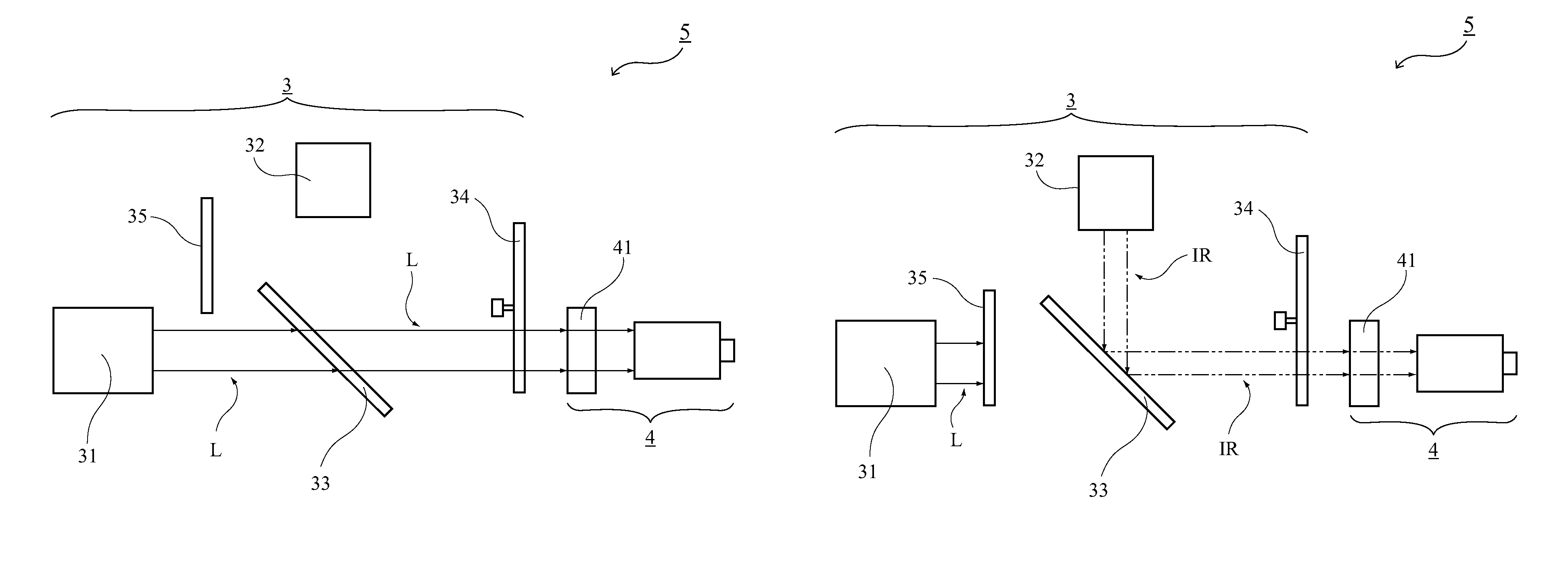
[0025]the present invention is shown in FIG. 3A and FIG. 3B. As shown in FIG. 3B, the first light source device 31 and the second light source device 32 emit a red light R, a green light G, a blue light B and an infrared light IR respectively by time sequence control. In reference to FIG. 3A, after being emitted by the first light source device 31 according to the time sequence, the red light R, the green light G and the blue light B pass through the first light guiding device 33 and are outputted to the light processing element 41 of the image-forming system 4 for processing. The red light R, the green light G and the blue light B are processed into a red light image, a green light image and a blue light image respectively by the light processing element 41, and are projected outward to form a visible light image through superposition. Then, subsequent to the first light source device 31, the second light source device 32 emits the infrared light IR. The infrared light IR is reflec...

third embodiment

[0039]It can also be readily inferred by those of ordinary skill in the art that the first light guiding device 33 of the third embodiment may have a dichroic layer with opposite characteristics and that the positions of the first light source device (the red light source 311, the green light source 312 and the blue light source 313 as shown in FIG. 5) together with the corresponding light processing elements 42a, 42b, 42c as well as the second light guiding device 36 may be exchanged with the positions of the second light source device 32 together with the corresponding light processing element 42d. In this way, the first light guiding device 33 can also reflect the visible light L generated by the first light source device to the image-forming system, and allow the infrared light IR generated by the second light source device 32 to pass therethrough to the image-forming system, thereby generating and projecting the visible light image and the infrared light image.

[0040]In the thir...


PUM


Abstract

An illumination system and a projection device comprising the same are provided. The projection device comprises an image-forming system and the illumination system. The illumination system comprises a first light source device, a second light source device and a first light guiding device. The first light source device generates a visible light, while the second light source device directly generates a substantially pure infrared light. The first light guiding device is adapted to guide the visible light and the infrared light to the image-forming system for processing to make the visible light form a visible light image and make the infrared light form an infrared light image.

Description

[0001]This application claims priority to Taiwan Patent Application No. 099127914 filed Aug. 20, 2010, the disclosures of which are incorporated herein by reference in their entirety.CROSS-REFERENCES TO RELATED APPLICATIONS[0002]Not applicable.BACKGROUND OF THE INVENTION[0003]1. Field of the Invention[0004]The present invention relates to an illumination system for a projection device, and more particularly, to an illumination system for a projection device adapted to generate a visible light image and an infrared light image.[0005]2. Descriptions of the Related Art[0006]Human eyes can only see the visible light with wavelength ranging from approximately 400 nm to 700 nm. However, at night or when the visible light becomes faint, light (e.g., moonlight or starlight) irradiated from the objects in the natural environment has wavelength mainly ranging from approximately 700 nm to 1,000 nm, so human eyes cannot see the objects in such environment. In particular, it is critical for mili...

Claims


Application Information

Patent Timeline
Patent Type & Authority Patents(United States)
IPC IPC(8): G03B21/26G09B19/16G03B21/20
CPCG03B21/2013G03B21/2066G03B21/2093G03B21/26G03B21/28G03B21/20
Inventor CHANG, KEH-SUSUN, FU-KUO
Owner DELTA ELECTRONICS INC
Why Eureka
Try Eureka