Method and system for exhaust gas recirculation

a technology of control system and exhaust gas, which is applied in the direction of machines/engines, mechanical equipment, non-fuel substance addition to fuel, etc., can solve the problems of engine misfire, torque and engine speed loss, engine damage, etc., and achieve the effect of increasing power outpu

Inactive Publication Date: 2014-05-20
FORD GLOBAL TECH LLC
View PDF23 Cites 21 Cited by
  • Summary
  • Abstract
  • Description
  • Claims
  • Application Information

AI Technical Summary

Benefits of technology

[0004]A low-pressure EGR system also increases the intake air temperature that is experienced by the compressor. If not controlled properly, the compressor outlet temperature may rise to levels that can degrade compressor components. A low-pressure EGR system may also contribute to a compressor surge condition, in which an unstable and inefficient air flow condition can reduce compressor performance and potentially damage compressor components.
[0007]For example, when a condensation condition exists, such as when an air intake temperature is below an intake temperature threshold, the EGR differential between the first compressor and the second compressor may be increased by reducing exhaust gas flow to the second compressor, and correspondingly increasing exhaust gas flow to the first compressor. In this manner, the amount of heated exhaust gas combined with intake air is increased, thereby increasing the air intake temperature at the compressor inlet and reducing the likelihood of condensation accumulation.
[0008]When a surge condition exists, such as when an estimated manifold pressure exceeds a pressure threshold and an estimated air flow downstream from the first compressor is below an air flow threshold, the EGR differential between first compressor and the second compressor may be decreased by increasing exhaust gas flow to the second compressor, and correspondingly decreasing exhaust gas flow to the first compressor. In this manner, the amount of exhaust gas combined with intake air is decreased, thereby decreasing the air flow into the first compressor inlet and reducing the likelihood of compressor damage due to a surge condition.
[0009]In another example, when an estimated compressor outlet temperature exceeds an outlet temperature threshold associated with potential damage to compressor components, the EGR differential between the first compressor and the second compressor may be decreased by increasing exhaust gas flow to the second compressor, and correspondingly decreasing exhaust gas flow to the first compressor. In this manner, the amount of heated exhaust gas combined with intake air is decreased, thereby decreasing the air intake temperature at the first compressor inlet and correspondingly decreasing the compressor outlet temperature, and reducing the likelihood of compressor degradation due to high temperatures.

Problems solved by technology

Utilizing separate EGR systems necessitates a footprint and packaging space large enough to accommodate components for both EGR systems.
With respect to a typical low-pressure EGR system in a turbocharged engine, a potential issue can arise when certain environmental conditions exist, such as low ambient air temperature and / or high humidity conditions.
Under certain operating conditions such as hard accelerations, the condensation may be dislodged, for example, from the EGR air cooler and may travel into a turbocharger compressor, potentially damaging compressor components.
The condensation may also continue into the combustion chambers of the engine causing performance issues, such as torque and engine speed losses, engine misfires and incomplete fuel burn.
If not controlled properly, the compressor outlet temperature may rise to levels that can degrade compressor components.
A low-pressure EGR system may also contribute to a compressor surge condition, in which an unstable and inefficient air flow condition can reduce compressor performance and potentially damage compressor components.

Method used


Image

  • Method and system for exhaust gas recirculation
  • Method and system for exhaust gas recirculation
  • Method and system for exhaust gas recirculation

Examples


Embodiment Construction

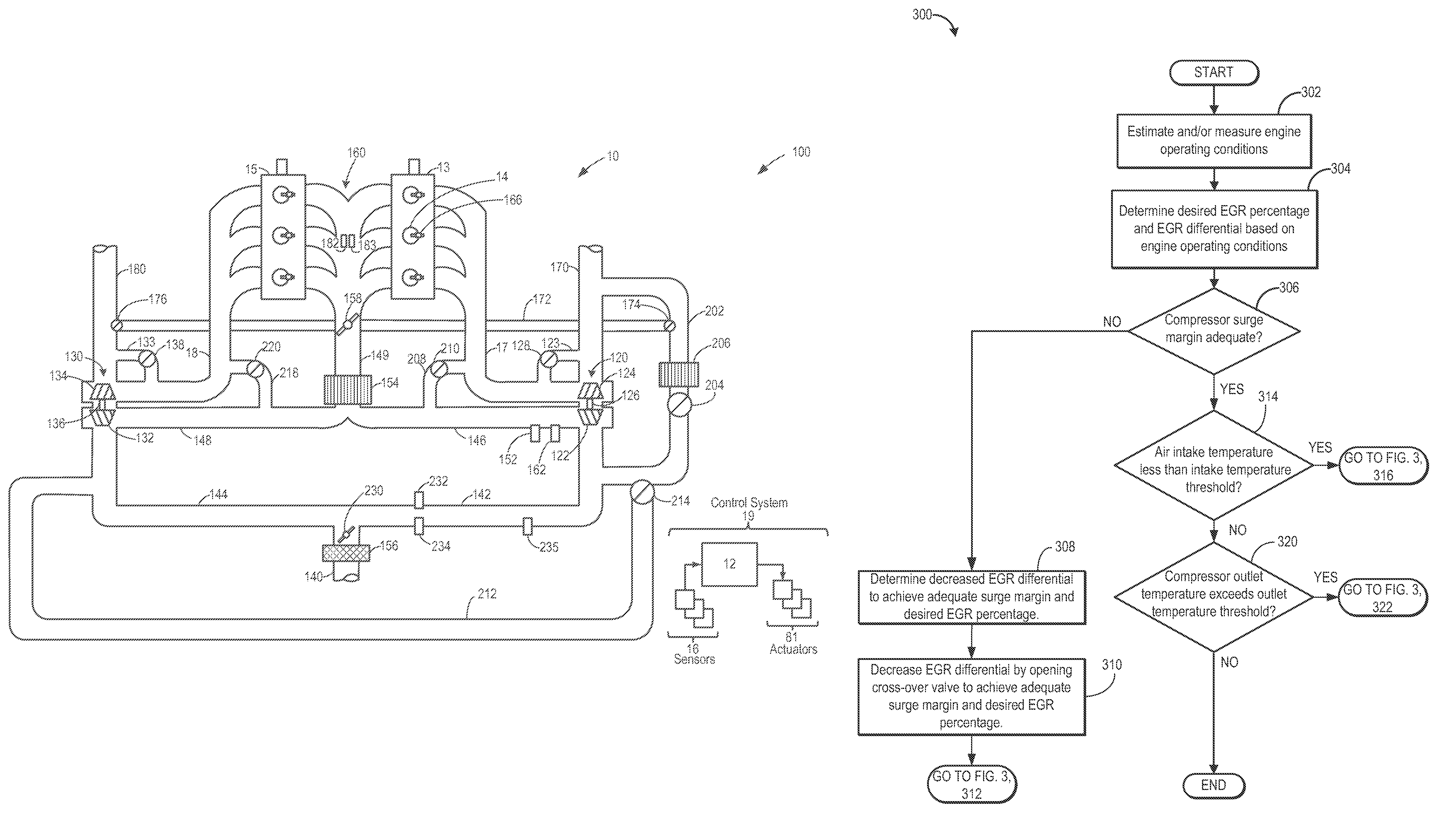
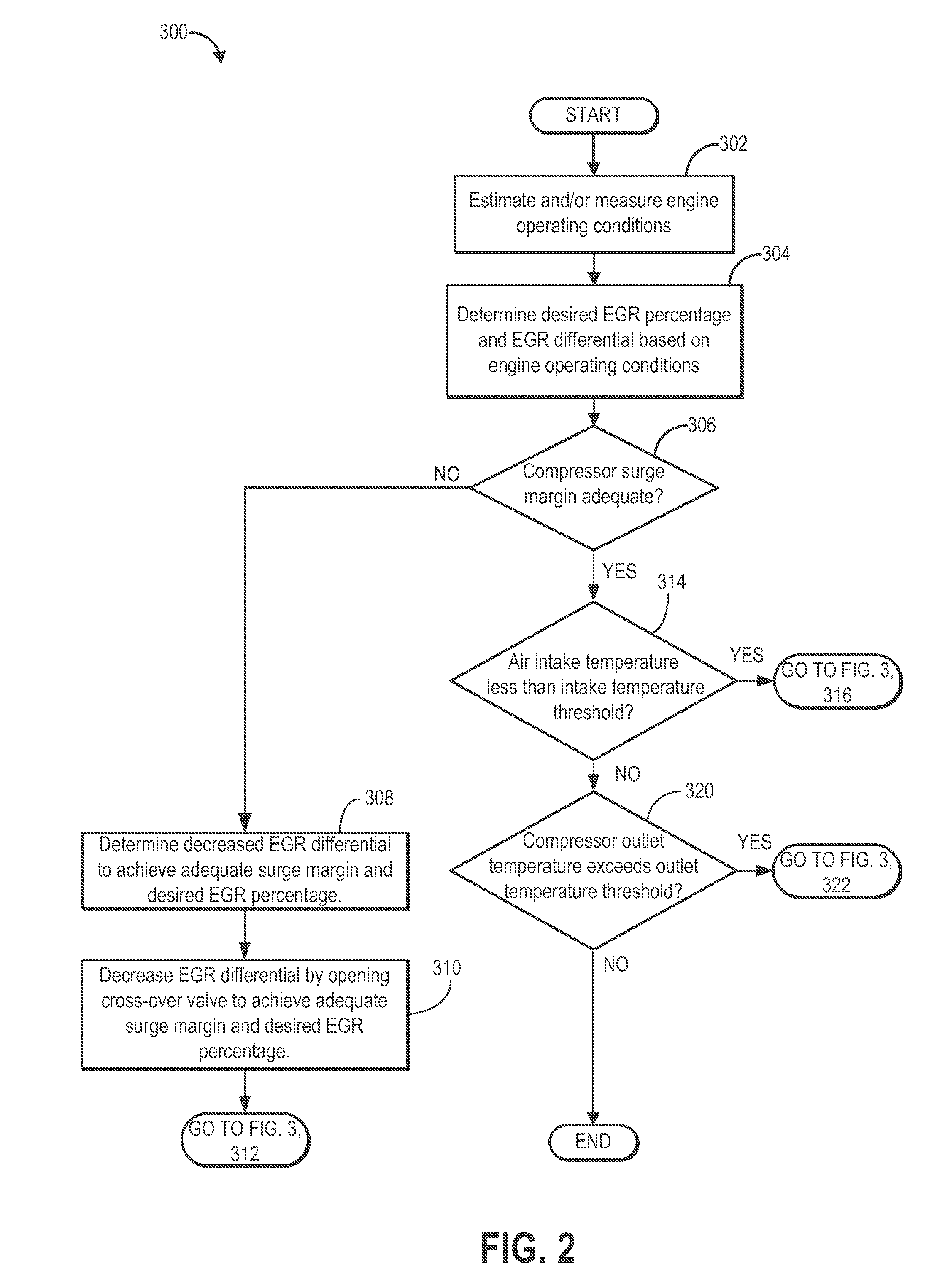
[0014]The following description relates to systems and methods for operating an engine including a first turbocharger having a first compressor and a second turbocharger having a second compressor (FIG. 1). Based on engine operating conditions, a desired EGR percentage and an EGR differential may be determined (FIG. 2). Further, based on a determination of whether an adequate surge margin exists, whether an air intake temperature is less than an intake temperature threshold, and whether a compressor outlet temperature exceeds an outlet temperature threshold, an EGR differential may be adjusted (FIGS. 2-3).

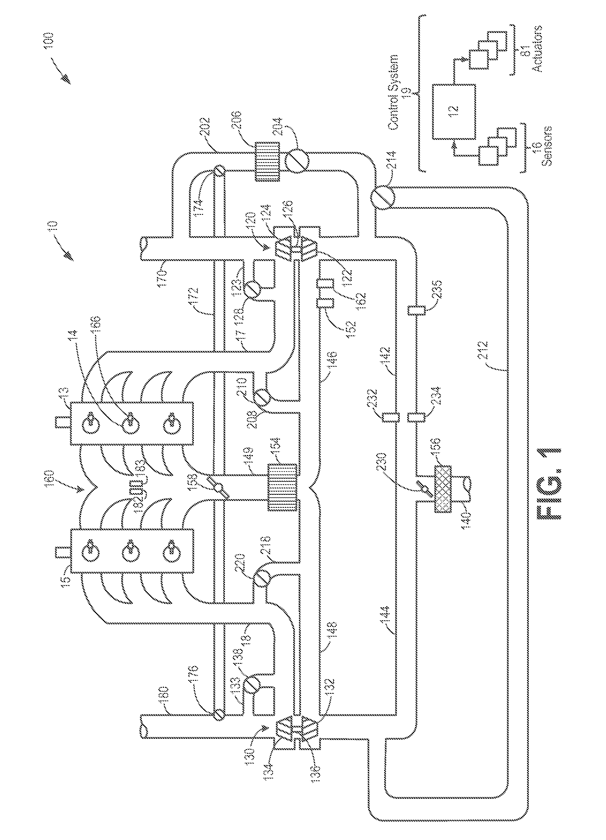
[0015]FIG. 1 shows a schematic depiction of an example turbocharged engine system 100 including a multi-cylinder internal combustion engine 10 and twin turbochargers 120 and 130. As one non-limiting example, engine system 100 can be included as part of a propulsion system for a passenger vehicle. Engine system 100 can receive intake air via intake passage 140. Intake passage 140 ca...


PUM


Abstract

Methods and systems are provided for an engine including a first turbocharger having a first compressor and a second turbocharger having a second compressor. An EGR differential between the first compressor and the second compressor may be increased under a condensation condition, and decreased under a surge condition. The EGR differential may also be decreased when a compressor outlet temperature exceeds an outlet temperature threshold.

Description

FIELD[0001]The present application relates to control systems for exhaust gas recirculation in a turbocharged engine system.BACKGROUND AND SUMMARY[0002]Engine systems may utilize one or more turbochargers to compress ambient intake air entering the engine to provide increased power output. Turbocharged engine systems may also be configured with one or more high-pressure and / or low-pressure exhaust gas recirculation (EGR) systems that recirculate at least a portion of the exhaust gas to the engine intake. In an engine system utilizing two turbochargers operating in parallel, separate EGR systems may be associated with each turbocharger. Utilizing separate EGR systems necessitates a footprint and packaging space large enough to accommodate components for both EGR systems.[0003]With respect to a typical low-pressure EGR system in a turbocharged engine, a potential issue can arise when certain environmental conditions exist, such as low ambient air temperature and / or high humidity condi...

Claims


Application Information

Patent Timeline
Patent Type & Authority Patents(United States)
IPC IPC(8): F02B33/44F02M25/07F02B33/00
CPCF02B37/001F02B37/12F02M25/0727Y02T10/121F02M25/0738F02M25/0744F02B29/0406F02M25/0713F02M25/0711F02M26/08F02M26/10F02M26/23F02M26/33F02M26/38F02D21/08F02D23/00F02B33/00F02B33/40F02B33/446F02B37/007F02B37/013F02B37/16F02B37/18Y02T10/12F02M26/06
Inventor STYLES, DANIEL JOSEPHBOYER, BRAD ALANMAKKAPATI, SATHEESH
Owner FORD GLOBAL TECH LLC
Why Eureka
Try Eureka