AC motor control device and AC motor driving system

a technology of ac motor and control device, which is applied in the direction of motor/generator/converter stopper, dynamo-electric gear control, motor/generator/converter stopper, etc., can solve the problems of difficult to obtain an inverse function, difficult to set the operation, and inability to describe the accuracy and usability of the approximate equation, so as to reduce the number of analyses and reduce the time and work necessary for setting data. , the effect o

Inactive Publication Date: 2014-06-03
HITACHI LTD
View PDF13 Cites 6 Cited by
  • Summary
  • Abstract
  • Description
  • Claims
  • Application Information

AI Technical Summary

Benefits of technology

[0126]According to the present invention the nonlinear state quantity of the AC motor can be set more accurately and simply. Particularly, it is possible to reduce the number of times of analyses and tests for preparing the table data and work and time necessary for setting data can be largely reduced.
[0128]Using the accurate state quantity in the torque control makes it possible to perform a torque control with a higher accuracy even in the magnetic saturated state such as a heavy load condition, so that the motor can be driven with a high response and a high efficiency.
[0129]In addition, using the accurate state quantity in the position sensor less control provides a more accurate rotor position estimation, so that a control performance of the position sensor less control can be increased.
[0130]In addition, because a function formula capable of obtaining an inverse function is used, it is possible to configure a motor model approximating the nonlinear characteristic of an actual motor inside a controller, so that it is possible to expand the position sensor less control with the motor model up to the magnetic saturation region.
[0132]As mentioned above, because the control characteristic at a heavy load is improved with a high accuracy, the AC motor to be controlled can be down-sized and decreased in cost.

Problems solved by technology

However, there is no description about accuracy and usability of the approximate equation, but Prior art 2 mainly describes the method of using a two-dimensional table data of the interlinkage flux.
In addition, because the indicated approximate equation of flux interlinkage is a quadratic function of the current, it is difficult to obtain an inverse function thereof.
When the table data is used, the number of pieces of the data increases to have a higher accuracy, so that the setting operation becomes complicated, and the number of times of analyses and tests for obtaining data increases.

Method used


Image

  • AC motor control device and AC motor driving system
  • AC motor control device and AC motor driving system
  • AC motor control device and AC motor driving system

Examples


first embodiment

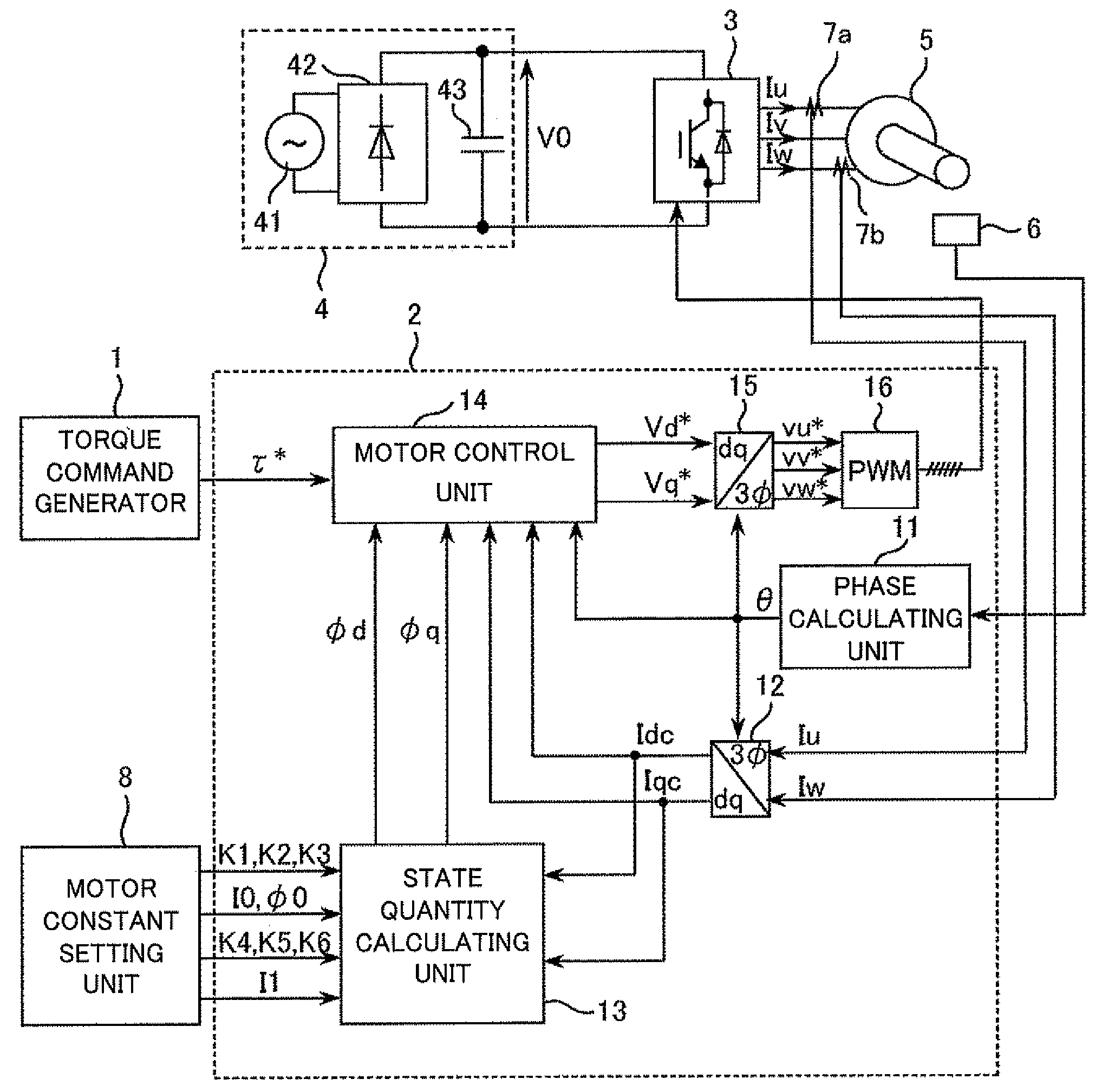
[0173]FIG. 1 is a block diagram showing a system configuration of an AC motor control device according to a first embodiment of the present invention. The control device according to the first embodiment includes a torque command generator 1 for providing a motor a torque command τ* to the motor, a controller 2 for calculating an AC applied voltage to the motor and converting it into a pulse width modulation signal (hereinafter abbreviated as PWM signal) to output the PWM signal, an inverter 3 driven by the PWM signal, a DC power supply 4 for supplying an electric power to an inverter 3, a permanent magnet type synchronous motor 5 to be controlled (hereinbelow, abbreviated as PM motor), a position detector 6 for detecting a rotor position of the PM motor 5, a current detector 7a for detecting a current Iu supplied to the PM motor 5 by the inverter 3 and a current detector 7b for detecting a current Iw, supplied to the PM motor 5 by the inverter 3, and a motor constant setting unit 8...

second embodiment

[0214]Will be described a second embodiment of the present invention.

[0215]In the second embodiment, the motor control unit 14 is replaced with a motor control unit 14a shown in FIG. 12.

[0216]FIG. 12 is difference from FIG. 2 in that the conversion coefficient 32 is omitted and a torque calculating unit 37 is provided to calculate a torque estimation value τc.

[0217]The state quantities 37φd, φq of the PM motor outputted by the state quantity calculating unit 13 and the detected currents Idc, Iqc are applied to the toque calculating unit 37 which calculates a torque estimation value τc with the functional formulas below.

τc=φd·Iqc−φq·Idc  (14)

[0218]The state quantities φd, φq of the PM motor outputted by the state quantity calculating unit 13, which is a feature of the present invention, are used for the torque estimation calculation as mentioned above, which provides the torque control with a high accuracy and high response even if the electric constants of the motor vary because the...

third embodiment

[0219]Will be described a third embodiment of the present invention.

[0220]In the first and second embodiments, the configurations with the position sensor and current sensor are exemplified. However, configuration of a position-sensor-less-and-current-sensor-type can be provided.

[0221]With reference to FIG. 13 will be described the third embodiment.

[0222]FIG. 13 is different from FIG. 1 as follows:

[0223]First, the torque command generator 1 is replaced with a speed command generator 1a. The motor control unit 14 is replaced with a motor control unit 14b. The position detector 6 and the phase calculating unit 11 are omitted, and the phase angle θdc is supplied by the motor control unit 14b.

[0224]Regarding the method of calculating and setting the state quantities φd, φq, the method described in the first embodiment is used.

[0225]Next, with reference to FIG. 14, will be described an operation of the motor control unit 14b.

[0226]The configuration of the motor control unit 14b in the ...


PUM


Abstract

The present invention relates to an AC motor control device and, particularly, to provide an AC control device capable of simply setting a state quantity of an AC motor non-linearly variable, in accordance with the motor driving state and using the setting in motor control, the present invention can be achieved by including a state quantity calculating unit (13, 13a, 13b, 13c) for calculating a state quantity corresponding to a coil interlinkage flux which is an internal quantity of the motor, calculating a setting value of the coil interlinkage flux defined on one axis out of two axes, that is, d and q axes, with a function formula using a current defined on the same one of the axes and a function formula using a state variable defined on the other one of the axes.

Description

TECHNICAL FIELD[0001]The present invention relates to an AC motor control device and particularly to setting a state quantity of an AC motor.BACKGROUND ART[0002]AC motors, particularly, permanent magnet synchronous motors have an expanded use in, for example, a home electric appliance field, an industrial use, and motor vehicle because of their small size and high efficiency. Particularly, products have increased in the number which has a sinusoidal-wave-conducting type of driving method in place of products having the square-wave-conducting type of driving method. And controllers have been increased in the number which are used for, for example, a rotor position estimation in the position-sensor-less control and a high accuracy torque control and require input of motor electric constant setting values such as resistance, inductance, and an induced voltage constant. Accordingly, if the motor electric constants are not accurately determined and inputted, this will largely influences ...

Claims


Application Information

Patent Timeline
Patent Type & Authority Patents(United States)
IPC IPC(8): H02P21/00H02P27/04H02P21/13H02P21/14H02P21/18H02P21/22H02P21/24H02P23/14H02P23/16H02P27/08H02P29/00H02P29/40H02P29/60H02P29/62H02P29/66
CPCH02P21/141H02P21/146H02P21/0042H02P21/26H02P21/18
Inventor NAKATSUGAWA, JUNNOSUKEIWAJI, YOSHITAKAIWASAKI, NORIHISANAGURA, HIROKAZU
Owner HITACHI LTD
Why Eureka
Try Eureka