Method of manufacturing a diffraction lens other than an aphakic intraocular lens

a technology of aphakic intraocular lens and a manufacturing method, which is applied in the direction of intraocular lens, instruments, spectales/goggles, etc., can solve the problems of reducing the contrast in the intermediate vision range, reducing the efficiency of diffraction lens, and increasing the difficulty of adjusting the aperture. effect of the lens eccentricity

Active Publication Date: 2014-06-17
MENICON CO LTD
View PDF16 Cites 10 Cited by
  • Summary
  • Abstract
  • Description
  • Claims
  • Application Information

AI Technical Summary

Benefits of technology

[0008]With the foregoing in view, it is accordingly an object of the present invention, to provide a novel method of manufacturing a diffraction lens that is capable of ensuring every multi-focusing effect more securely, while reducing the impact of aperture changes and lens eccentricity.
[0012]According to the manufacturing method of this invention, at least two foci can be generated by each first order diffracted light of at least two reliefs. With this arrangement, in case of using bifocal contact lenses for presbyopia, for example, as an optical material, the 0th order light by the refractive surface of the lens, for example, is set to focus for far vision, while the first order light by one of the two reliefs is set to focus for near vision, in addition to having the other first order light set to focus for intermediate vision. This makes it possible to obtain good diffraction intensity in the intermediate vision range in addition to the far and near vision ranges, thus providing a contact lens capable of delivering good vision in the intermediate range. The word “relief” in this invention refers to a jagged form.
[0013]According to the diffraction lens manufactured by the present manufacturing method, various types of reliefs are set to overlap with each other. This allows the first order diffracted light to be generated by each relief in the entire area where various types of reliefs are overlapped. Therefore, unlike a diffraction lens on which different reliefs are set up in each area, as described in the above Patent Document 2 for example, it is now possible to obtain a diffraction lens with an unprecedented new optical properties, whereby the desired optical properties are more securely obtained by restricting relative variations of the diffraction intensity in a particular area caused by changes in diameter of incident light beam following changes in aperture and the eccentricity of the lens and the like.
[0014]Besides, especially by the present manufacturing method, a synchronous structure is set up where grating pitches of other reliefs are overlapped periodically with each grating pitch of the relief having the maximum grating pitch among the reliefs set up in overlap. That is, the synchronous structure is set up where zone radii of other reliefs are overlapped periodically with each zone radius of the relief having the maximum grating pitch. Here, the word “grating pitch” means a width of each relief between the ridge and valley lines in the radial direction. The “zone radius” refers to a radius of a ridge or valley line located on the outer side of the concentric center measured from the concentric center in the zone between the ridge and valley lines of each relief extending concentrically. Also, “concentrically” means a state of multiple streaks in forms of circles or something similar such as ovals extending in an annular pattern centered on an optical axis or an eccentric axis. Also, the “radial direction of the diffraction lens” mentioned in the claims of this invention means a radial direction centered on the optical axis, and in case the optical axis is off the geometric center of the lens, it is not necessarily identical to the radial direction of the lens relative to its outer peripheral configuration. This makes it possible to distinctly generate a peak of diffraction intensity of the first order diffracted light of each relief and to obtain a multitude of foci more certainly. In other words simply overlapping various types of reliefs cannot clearly obtain a peak of diffraction intensity of any relief and results in generating peaks of unintended order of light beams, while increasing the quantity of glare caused by stray light beams. On the contrary, according to the present manufacturing method, diffraction intensity can be allocated effectively to the first order diffracted light of other reliefs by synchronizing grating pitches of different relief patterns, thus reducing the intensity of unnecessary nth order diffracted light beams including second order diffracted light. As a result, the quantity of stray light and so forth can be lowered and the glare and the like can be reduced.

Problems solved by technology

For instance, bifocal lenses assign the 0th order light and first order light for far vision and near vision respectively, as described above, resulting in a problem getting more recognized these days that allocating energy to the mid-section between the 0th order and first order light becomes more difficult and the contrast in the intermediate vision range gets too low.
However, the diffraction lens described in Patent Document 2 had a risk of failing to achieve the desired focal effect when the diameter of incident light beam varies by aperture or due to pupil shrinkage of human eyes.
Especially in case of an ophthalmic lens, it is not necessarily possible to stably place a diffraction lens in the desired position relative to the pupil, even if it is designed with consideration of physiological pupil diameter of human eyes, which poses a risk of failing to achieve the desired focal effect.Patent Document 1: U.S. Pat. No. 5,121,980Patent Document 2: U.S. Pat. No. 7,188,949

Method used


Image

  • Method of manufacturing a diffraction lens other than an aphakic intraocular lens
  • Method of manufacturing a diffraction lens other than an aphakic intraocular lens
  • Method of manufacturing a diffraction lens other than an aphakic intraocular lens

Examples


first embodiment

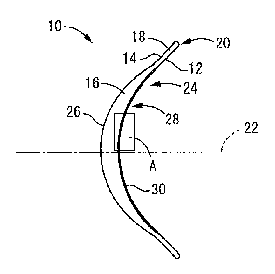
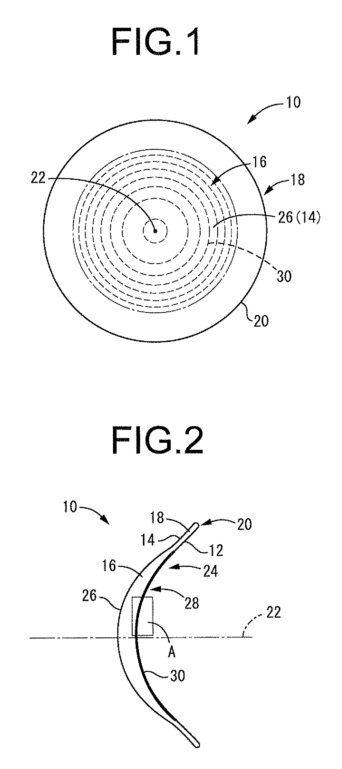
[0110]First of all, FIG. 1 shows a front view diagram of a contact lens 10 as a first embodiment related to the diffraction lens in this invention, and FIG. 2 shows a side view of the contact lens 10. Here in FIGS. 1 and 2, a relief pattern 30 described later is shown with its size exaggerated for better understanding.

[0111]The contact lens 10 comprises a lens's rear surface 12 in an approximate concave shape of a sphere as a whole and a lens's front surface 14 with an approximate convex shape of a sphere as a whole, and is, in its entirety, in an approximate shape of a spherical shell. Also, the center part of the contact lens 10 is made to be an optical part 16 in a round shape in front view, which can exert the effect of prescribed vision corrections on the wearer. Furthermore, the peripheral part of the contact lens 10 located around the optical part 16 is made to be a peripheral part 18 in an annular shape in front view, which securely holds the contact lens 10 at a given posit...

second embodiment

[0164]First, FIG. 12 shows a relief profile of a relief pattern 50 as this invention. In the present embodiment, a synchronous structure is set up where two reliefs with the dioptric power at +3.0 D for near vision and the other at +1.0 D for intermediate vision are periodically overlapped. By the way, the relief profile of the present embodiment is the one obtained under the following conditions:

[0165]Radius of the base curve of the rear optical part=8.000 mm

[0166]Dioptric power of the rear optical part=+5.0 D

[0167]Refractive index of the lens material=1.500

[0168]Refractive index of the surrounding medium=1.336

[0169]Designed wavelength=500 nm

[0170]Zone constant of the relief for near vision ‘a’=1

[0171]Meanwhile, the grating pitch is larger in the relief for intermediate vision than in the relief for near vision.

[0172]Especially in the present embodiment, two relief depths of the relief for near vision are provided per each zone of the relief for intermediate vision, and these three...

third embodiment

[0175]Next, FIG. 14 shows a relief profile of a relief pattern 60 as this invention. In the present embodiment, a synchronous structure is set up where two reliefs with the dioptric power at +3.0 D for near vision and at +1.0 D for intermediate vision are periodically overlapped. Meanwhile, the grating pitch is larger in the relief for intermediate vision than in the relief for near vision.

[0176]In the present embodiment, two relief depths of the relief for near vision are provided per each zone of the relief for intermediate vision, and these three zones in total are formed, that is, in one out of three zone radii of the relief for near vision, the zone radius of the relief for intermediate vision is made equal to that of the relief for near vision. And, in each zone of the relief for intermediate vision composed of an overlap of reliefs for near vision, the height of the relief depth of the relief for near vision located between the relief depths of the relief for intermediate vis...


PUM


Abstract

A novel manufacturing method for a diffraction lens, whereby aperture and eccentricity effects can be suppressed and any multi-focusing effect can also be obtained in a more stable manner. A synchronous structure is set up where at least two reliefs whose first order diffracted lights give respective focal distances different from one another are set to overlap with each other in at least a part of an area in a radial direction of a diffraction lens, and with respect to every grating pitches of one relief having the maximum grating pitch among the reliefs set up in overlap, grating pitches of another relief are overlapped periodically; and the resulting relief pattern is formed on a surface of an optical material.

Description

TECHNICAL FIELD[0001]This invention relates to a method of manufacturing a diffraction lens and to a diffraction lens with a novel structure that can be favorably manufactured thereby.BACKGROUND ART[0002]Conventionally, optical lenses such as glasses, contact lenses, camera lenses, and pickup lenses for optical discs including compact discs have been used in various fields. Under these circumstances, lenses having multiple foci (multi-focus lenses) that can accommodate for both far vision and near vision in glasses, contact lenses and the like for presbyopia, for example, are sometimes required.[0003]As such a multi-focus lens, a diffraction lens such as that disclosed in Patent Literature 1, for example, is known to the public. The diffraction lens described in Patent Document 1 is provided with a diffraction grating having a relief on the lens surface, and is allowed to form two foci by the 0th order light and first order diffracted light taking advantage of the diffraction phenom...

Claims


Application Information

Patent Timeline
Patent Type & Authority Patents(United States)
IPC IPC(8): G02B5/18
CPCG02C2202/20A61F2/1602G02B5/1895G02C7/042G02C7/044A61F2/1654G02B5/1885
Inventor KOBAYASHI, ATSUSHISUZUKI, HIROAKIANDO, ICHIRO
Owner MENICON CO LTD
Why Eureka
Try Eureka