Far infrared ray ceramic bulb structure

a ceramic bulb and infrared ray technology, applied in the direction of gas-filled discharge tubes, semiconductor devices of light sources, lighting and heating apparatus, etc., can solve the problems of low whole energy conversion efficiency, or specifically much less than 50%, serious safety problems, and limited practical application, so as to improve stability and light-emitting efficiency, reduce the working temperature of light-emitting elements, and increase the lifetime and safety

Inactive Publication Date: 2014-06-24
JINGDEZHEN FARED TECH
View PDF10 Cites 1 Cited by
  • Summary
  • Abstract
  • Description
  • Claims
  • Application Information

AI Technical Summary

Benefits of technology

[0009]Therefore, the working temperature of the light emitting element is reduced and the stability and the efficiency of light emitting are improved to increase the lifetime and the safety.

Problems solved by technology

Therefore, the whole efficiency of energy conversion is low, or specifically much lower than 50%.
As a result, the practical application is greatly limited.
Besides, the PTC heating ceramic and the nickel-chromium wire in contact with water will cause explosion, and produces serious problems for safety.

Method used


Image

  • Far infrared ray ceramic bulb structure
  • Far infrared ray ceramic bulb structure
  • Far infrared ray ceramic bulb structure

Examples


first embodiment

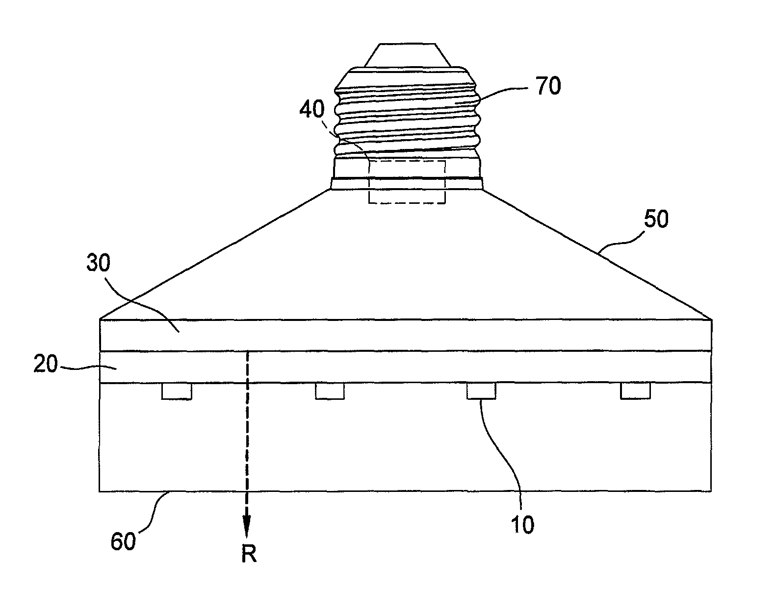
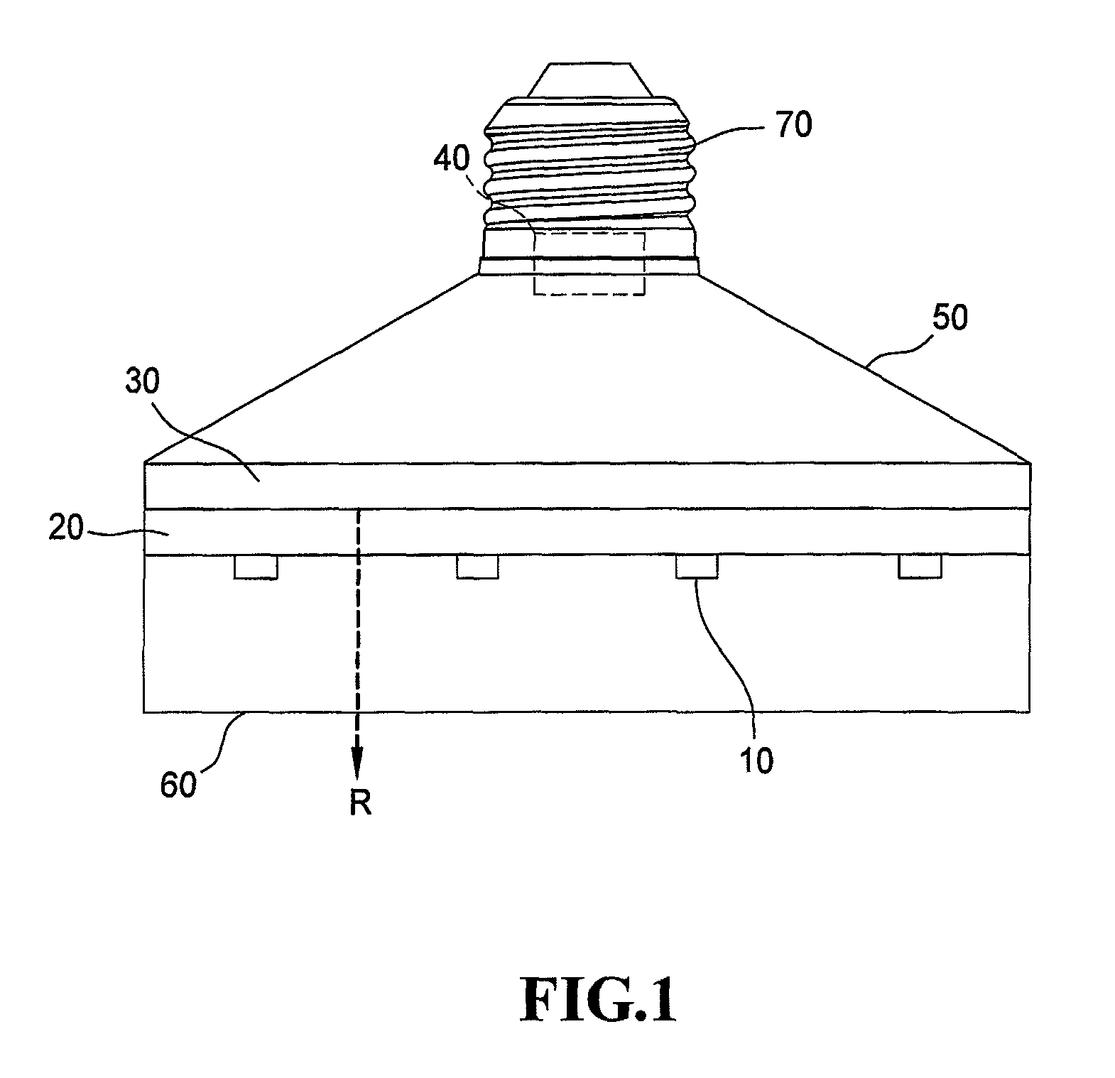
[0018]FIG. 1 clearly illustrates a far infrared ray ceramic bulb structure according to the present invention, and includes a light emitting element 10, a ceramic substrate 20, a far infrared thermal radiation film 30, a circuit unit 40, a bulb shell 50, a bulb shade 60 and a connector 70. The far infrared ray ceramic bulb structure of the present invention uses the light emitting element 10 to produce light, and the far infrared thermal radiation film 30 to emit far infrared ray R, which has a wavelength primarily within the range of 4 to 400 μm, and especially 6 to 14 μm.

[0019]The light emitting element 10 consists of an LED (light emitting diode) chip.

[0020]The ceramic substrate 20 has an upper surface and a lower surface. The light emitting element 10 is formed on a sapphire substrate (not shown) and is connected to the lower surface of the ceramic substrate 20. The far infrared thermal radiation film 30 is formed on the upper surface of the ceramic substrate 20. The circuit uni...

second embodiment

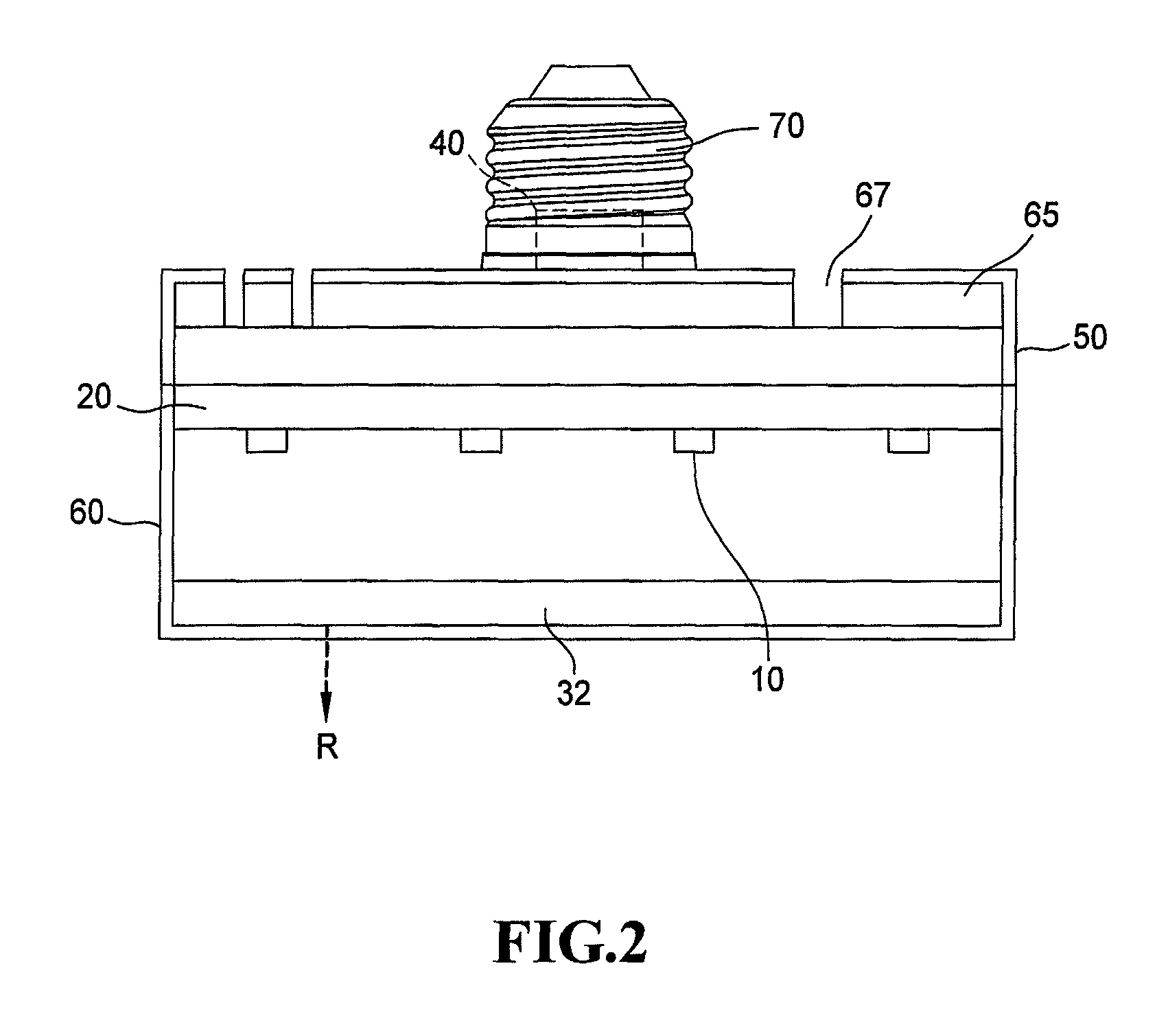
[0026]FIG. 2 illustrates the far infrared ray ceramic bulb structure according to the present invention. As shown in FIG. 2, the far infrared ray ceramic bulb structure of the present invention includes the LED chip 10, the ceramic substrate 20, the far infrared thermal radiation film 32, the circuit unit 40, the bulb shell 50, the bulb shade 60, the nano-enamel heat dissipation cover 65 and the connector 70. The far infrared ray ceramic bulb structure uses the LED chip 10 to emit light and the far infrared thermal radiation film 32 to generate far infrared ray R.

[0027]The far infrared ray ceramic bulb structure in FIG. 2 is similar to the first embodiment of the far infrared ray ceramic bulb structure, and the primary difference is that the far infrared thermal radiation film 32 is formed on the upper surface of the bulb shade 60, that is, the upward surface in FIG. 2.

[0028]Another difference is that the bulb shell 50 is connected to the connector 70 and encloses the upper surface ...

fourth embodiment

[0033]As shown in FIG. 5, the far infrared ray ceramic bulb structure according to the present invention includes the LED chip 10, the ceramic substrate 20, the far infrared thermal radiation film 30, the circuit unit 40, the bulb shell 50, the bulb shade 60 and the connector 70. The far infrared ray ceramic bulb structure uses the LED chip 10 to emit light and the far infrared thermal radiation film 30 generates far infrared ray R with a wavelength within the range of 4 to 400 μm, and especially 6 to 14 μm.

[0034]The far infrared ray ceramic bulb structure in FIG. 5 is similar to the far infrared ray ceramic bulb structure of the first embodiment in FIG. 1. The primary difference between the fourth and first embodiments is that the far infrared thermal radiation film 30 of the fourth embodiment is formed under the ceramic substrate 20 and on the LED chip 10, and the heat generated by the circuit unit 40 is directly transferred downwards by far infrared thermal radiation R direction....


PUM

PropertyMeasurementUnit
temperatureaaaaaaaaaa

Abstract

A far infrared ray ceramic bulb structure includes a light emitting element under a ceramic substrate, a far infrared thermal radiation film on the ceramic substrate, a circuit unit, a bulb shell, a bulb shade and a connector connected to an external power supply. The circuit unit in the connector is electrically connected to the light emitting element and the connector. The bulb shade encloses the light emitting element and the ceramic substrate. The bulb shell is connected to the connector and encloses the far infrared thermal radiation film. The far infrared thermal radiation film propagates the heat generated by the light emitting element by far infrared thermal radiation. The working temperature of the light emitting element is reduced and the stability and the efficiency of light emitting are improved to increase the lifetime and the safety.

Description

BACKGROUND OF THE INVENTION[0001]1. Field of the Invention[0002]The present invention generally relates to a ceramic bulb structure, and more specifically to a far infrared ray ceramic bulb structure having a light emitting element to generate far infrared ray.[0003]2. The Prior Arts[0004]According to studies from many colleges and research institutes around the world, water molecules tends to vibrate at the specific frequency of about 1012 / sec when illuminated by far infrared light. Such specifically vibrating water molecules can generate corresponding energy as heat to warm up human tissues, swell the blood vessels and speed up the blood flow so that it is possible for internal tissues to exercise. More specifically, when the water molecules start to vibrate upon being illuminated by far infrared ray, the chemical bond of hydrogen and oxygen in water molecule produces three types of motions, including compression, extension and rotation so as to break the strong hydrogen bonding a...

Claims


Application Information

Patent Timeline
Patent Type & Authority Patents(United States)
IPC IPC(8): H01J7/24F21V9/16
CPCH05B37/02A61N2005/0651A61N2005/066F21K9/13F21Y2101/02H05K1/0209H05K1/0212H05K1/0306H05K2201/10106F21K9/23F21Y2115/10H05B47/10
Inventor CHEN, JEONG-SHIUN
Owner JINGDEZHEN FARED TECH
Why Eureka
Try Eureka