
Method and apparatus for monitoring and mitigating stray electrical energy

a technology of electrical energy and monitoring method, applied in the direction of electrostatic charge, application, animal watering devices, etc., can solve the problems of defective equipment, unbalanced multi-phase electrical equipment, motors, generators, etc., and achieve the effect of reducing the risk of electrical energy loss

Active Publication Date: 2014-06-24
STRAUBHAAR JESSE
View PDF5 Cites 1 Cited by
  • Summary
  • Abstract
  • Description
  • Claims
  • Application Information

AI Technical Summary

Benefits of technology

[0006]Although the stray electrical energy is typically imperceptible to humans or animals, it is possible that stray electrical energy of sufficient amplitude may exist to be felt by or cause irritation to humans or to the animals. Stray electrical energy may travel between buildings and aggregate from multiple buildings to create a potentially unsafe or unpleasant environment. For example, animal water tanks are often metallic. Further, the water tanks may be fed by water pumped from a central source or from a well and carried through metal pipes. Stray electrical energy may be conducted through the water, pumps, pipes, water tanks, or a combination thereof into the animals. The effects of the stray electrical energy on animals have been reported to range from a minor irritation to causing sickness or death of an animal. Accurate measuring and recording of stray electrical energy can help in mitigating this energy.
[0009]Therefore, it is a primary object and feature of the present invention to provide an improved method of measuring and recording stray electrical energy, especially over a significant geographical region, to identify areas of interest having higher levels of stray voltage and / or leakage current and to minimize the level of stray electrical energy in the identified areas.

Problems solved by technology

Stray voltages may be produced, for example, by improper grounding of electrical equipment, unbalanced multi-phase electrical equipment such as motors, generators, and transformers, or defective equipment.
However, if any of the above-mentioned conditions exist, there is the possibility of a voltage potential existing on the ground conductor and being passed into the ground.
Deterioration or failure of an electrical device may create the unintended conduction.
Unintended conduction also occurs, for example, due to non-ideal behavior of electrical components such as diodes, transistors, and capacitors.
The electrical equipment may be spread out across several buildings and is often present in a dirty and wet environment.
The harsh environment has the potential for excessive wear, corrosion, and / or failure of the electrical equipment.
Prior to failure of electrical equipment, the equipment may operate in a state which introduces stray voltage and / or leakage currents onto ground conductors.
Although the stray electrical energy is typically imperceptible to humans or animals, it is possible that stray electrical energy of sufficient amplitude may exist to be felt by or cause irritation to humans or to the animals.
Stray electrical energy may travel between buildings and aggregate from multiple buildings to create a potentially unsafe or unpleasant environment.
The effects of the stray electrical energy on animals have been reported to range from a minor irritation to causing sickness or death of an animal.
However, measuring stray voltage in this manner is not without its drawbacks.
Further, the single reading captures the stray voltage at only a single instant and fails to capture trends or peak values of the stray voltage.
A high level of voltage with a low current, may present little danger, while a relatively low level of voltage with a high current may present a significant danger.

Method used


Image

  • Method and apparatus for monitoring and mitigating stray electrical energy
  • Method and apparatus for monitoring and mitigating stray electrical energy
  • Method and apparatus for monitoring and mitigating stray electrical energy

Examples


Embodiment Construction

[0027]The various features and advantageous details of the subject matter disclosed herein are explained more fully with reference to the non-limiting embodiments described in detail in the following description.

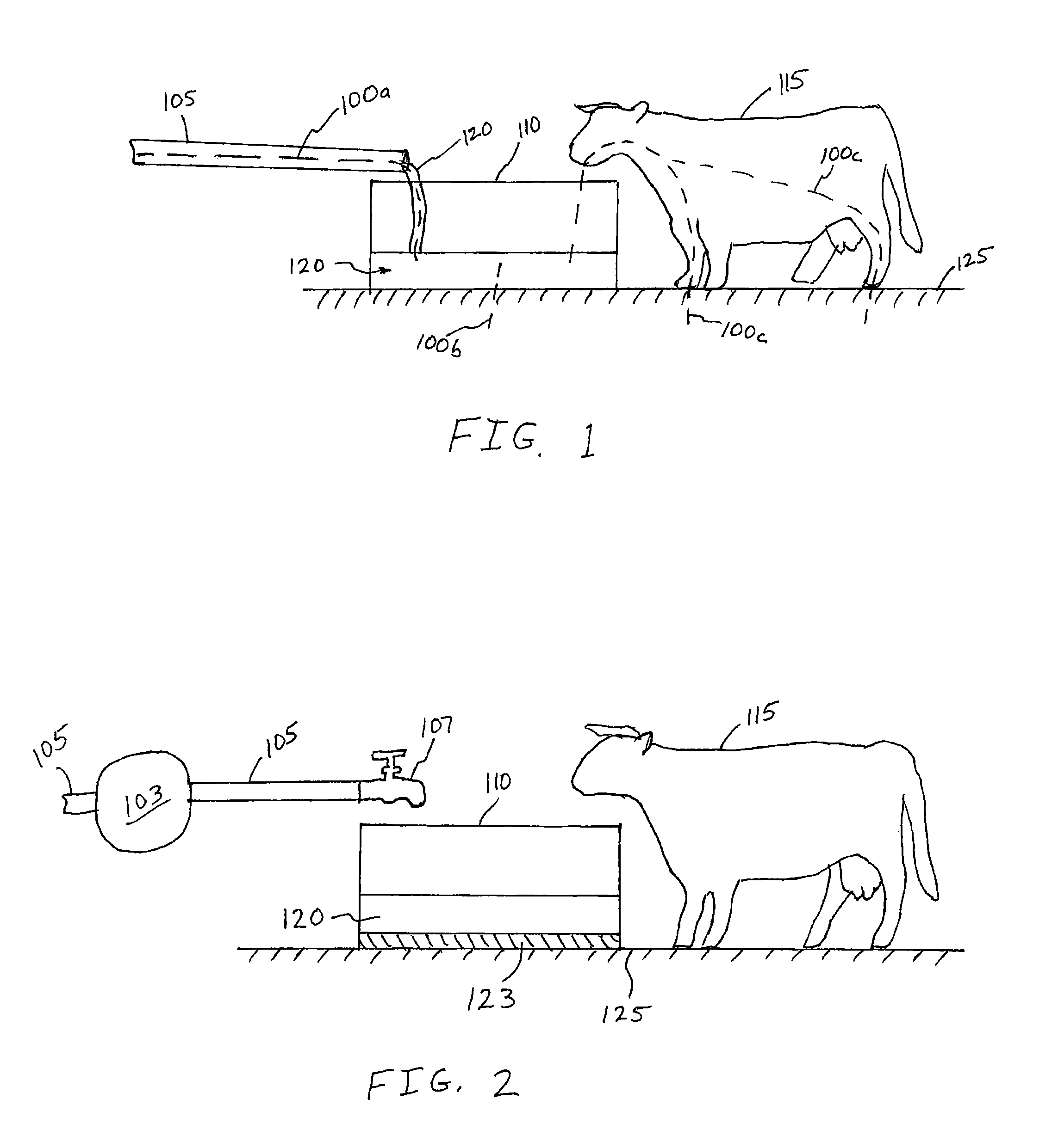
[0028]Referring to FIG. 1, an exemplary environmental view illustrates electrical conduction paths 100a-100c of leakage current from a water pipe 105 through a water tank 110 and to an animal 115. Typically, the water pipe 105 and water tank 110 are made of metal and are, therefore, electrically conductive. Water 120 is also electrically conductive. Consequently, if water 120 is flowing from the water pipe 105 into the water tank 110, a conduction path 100a is established from the water pipe 105 into the water tank 110. If an animal 115 drinks from the water tank 110 as water 120 is flowing from the water pipe 105, another conduction path 100c is established from the water tank 110 through the animal 115 to ground 125. Additionally, the water tank 110 is commonly resting dir...


PUM


Abstract

A system and method for monitoring and mitigating leakage currents. The data acquisition system records data from multiple monitoring locations over extended periods of time to identify stray voltage and / or leakage currents present at the monitoring location. The data is processed to identify trends in the stray voltage and / or leakage currents and to suggest methods for mitigating the same.

Description

CROSS-REFERENCE TO RELATED APPLICATIONS[0001]This application claims priority from U.S. Provisional Patent Application Ser. No. 61 / 355,353 filed on Jun. 16, 2010, the entirety of which is expressly incorporated by reference herein.FIELD OF THE INVENTION[0002]The subject matter disclosed herein relates generally to monitoring stray electrical energy, such as stray voltage and leakage currents, and in particular, to a method of monitoring and recording stray electrical energy over a large region to identify and mitigate the stray electrical energy.BACKGROUND AND SUMMARY OF THE INVENTION[0003]Stray electrical energy is often identified as “stray voltage.” Stray voltages describe voltages that exist between two objects that should not have a voltage difference between them. Stray voltages may be produced, for example, by improper grounding of electrical equipment, unbalanced multi-phase electrical equipment such as motors, generators, and transformers, or defective equipment. Electrical...

Claims


Application Information

Patent Timeline
Patent Type & Authority Patents(United States)
IPC IPC(8): H02H1/00
CPCA01K29/00A01K7/00
Inventor STRAUBHAAR, JESSE
Owner STRAUBHAAR JESSE
Learn More