Roller bearing, retainer segment of roller bearing for supporting main shaft of wind-power generator, and main shaft support structure of wind-power generator

a technology of wind-power generator and retainer segment, which is applied in the direction of machine/engine, bearing unit rigid support, electric generator control, etc., can solve the problem of reducing the circumferential range of clearance, the size of the roller bearing itself, and the limit of so as to reduce the thermal linear expansion coefficient and prevent the function of the roller bearing including such retainer segment from being lowered

Active Publication Date: 2014-07-01
NTN CORP
View PDF48 Cites 5 Cited by
  • Summary
  • Abstract
  • Description
  • Claims
  • Application Information

AI Technical Summary

Benefits of technology

[0010]It is an object of the present invention to provide a roller bearing capable of preventing its function from being lowered.
[0011]It is another object of the present invention to provide a roller bearing capable of preventing a retainer segment from being damaged and enabling a roller to roll smoothly.
[0012]It is still another object of the present invention to provide a retainer segment of a roller bearing for supporting a main shaft of a wind-power generator capable of preventing a function of the bearing from being lowered.

Problems solved by technology

Since a roller bearing to support a main shaft of a wind-power generator provided with a blade for receiving wind has to receive a high load, the roller bearing itself is large in size.
Thus, since the components such as a roller and a retainer that compose the roller bearing are large in size also, it is difficult to produce and assemble the components.
However, there is a limit of reducing the circumferential range of the clearance in the case of the retainer segment formed of the resin due to thermal expansion.

Method used


Image

  • Roller bearing, retainer segment of roller bearing for supporting main shaft of wind-power generator, and main shaft support structure of wind-power generator
  • Roller bearing, retainer segment of roller bearing for supporting main shaft of wind-power generator, and main shaft support structure of wind-power generator
  • Roller bearing, retainer segment of roller bearing for supporting main shaft of wind-power generator, and main shaft support structure of wind-power generator

Examples


Embodiment Construction

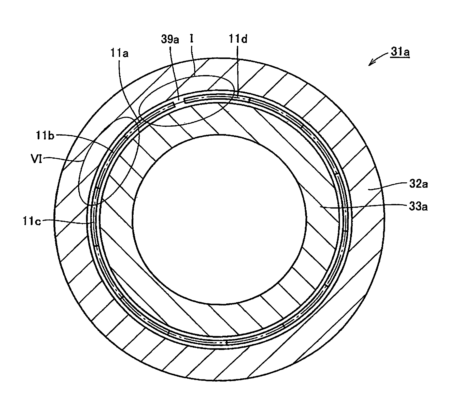
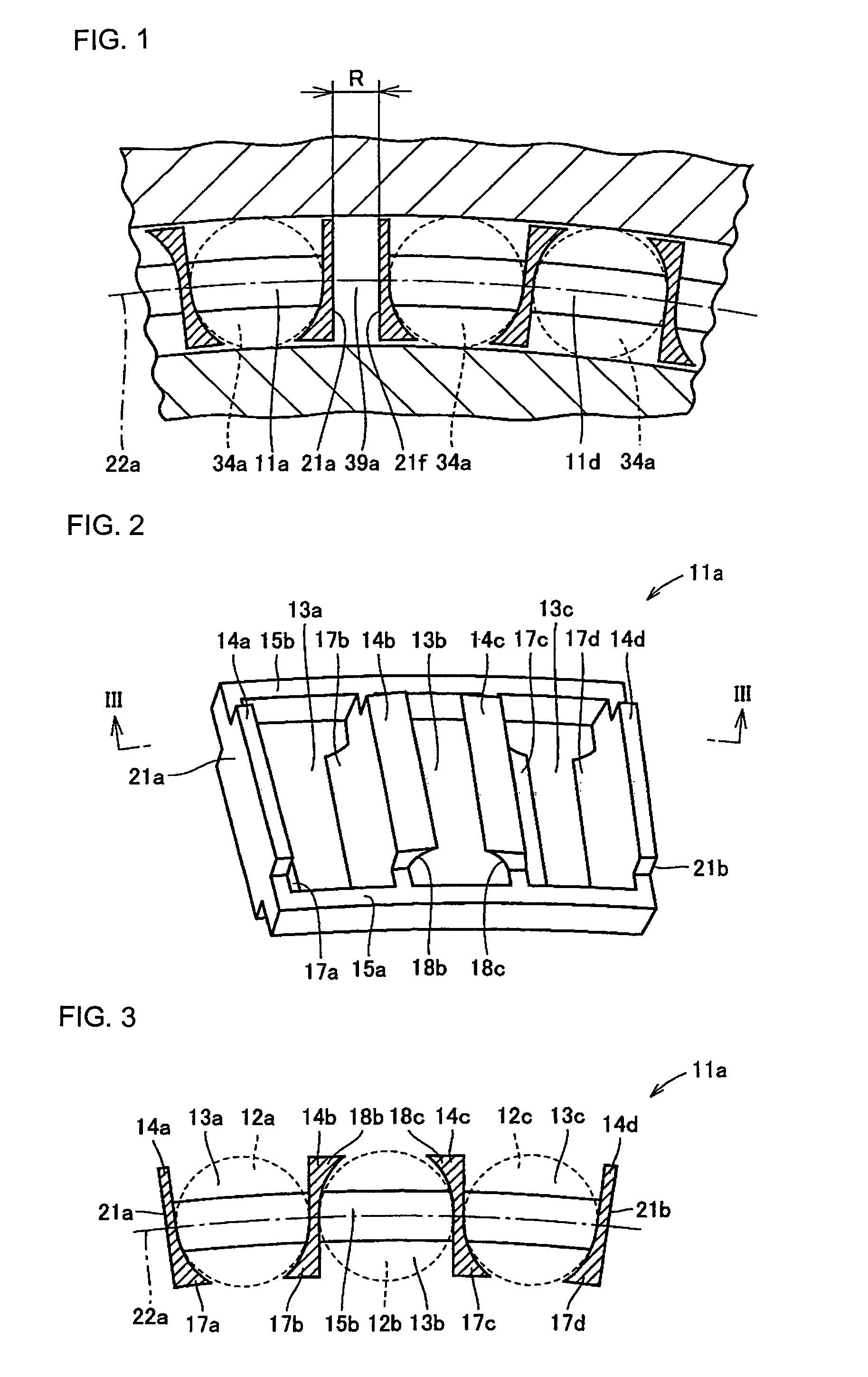
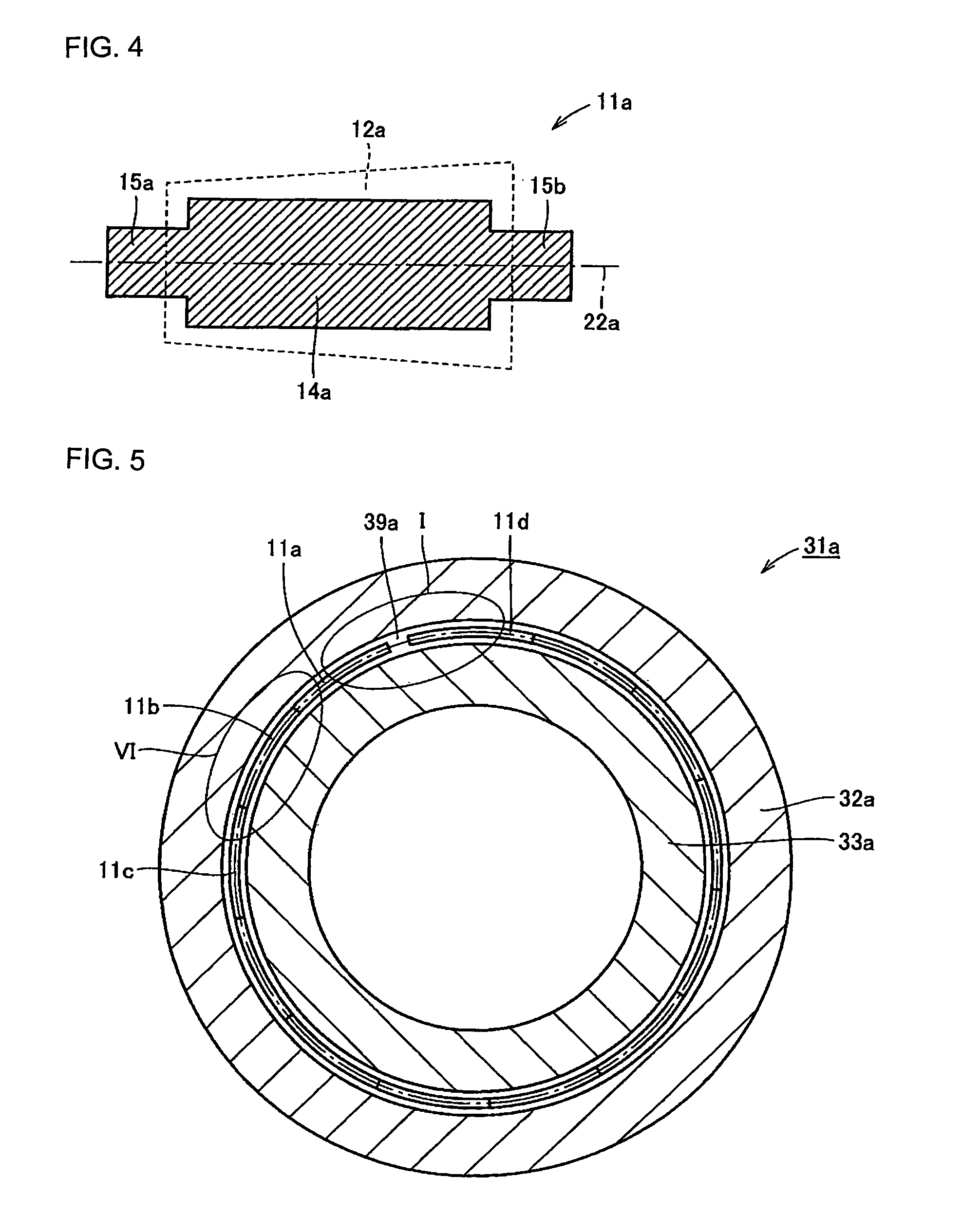
[0101]Embodiments of the present invention will be described with reference to the drawing hereinafter. FIG. 2 is a perspective view showing a retainer segment 11a provided in a tapered roller bearing according to one embodiment of the present invention, to support a main shaft of a wind-power generator. FIG. 3 is a sectional view showing the retainer segment 11a shown in FIG. 2 cut by a plane containing a line III-III in FIG. 2 and crossing a rotation axis of the bearing at right angles. FIG. 4 is a sectional view showing the retainer segment 11a shown in FIG. 2 cut by a plane passing through the center of a column part 14a and crossing a circumferential direction at right angles. In addition, a plurality of tapered rollers 12a, 12b, and 12c retained by the retainer segment 11a are shown by dotted lines in FIGS. 3 and 4 so as to be easily understood. In addition, a PCD 22a is shown by a one-dot chain line.

[0102]First, a constitution of the retainer segment 11a contained in the tape...


PUM

PropertyMeasurementUnit
timeaaaaaaaaaa
contact angleaaaaaaaaaa
thermal linear expansion coefficientaaaaaaaaaa

Abstract

A tapered roller bearing (31a) has a plurality of retainer segments (11a, 11d) each having a pocket to house a tapered roller (34a), and arranged so as to be continuously lined with each other in a circumferential direction between an outer ring (32a) and an inner ring (33a). The retainer segment (11a, 11d) is formed of a resin containing a filler material to lower a thermal linear expansion coefficient. In addition, a clearance (39a) is provided between the first retainer segment (11a) and the last retainer segment (11d) after the plurality of retainer segments (11a, 11d) have been arranged in the circumferential direction without providing any clearance. Here a circumferential range (R) of the clearance (39a) is larger than 0.075% of a circumference of a circle passing through a center of the retainer segment (11a, 11d) and smaller than 0.12% thereof at room temperature.

Description

TECHNICAL FIELD[0001]The present invention relates to a roller bearing, a retainer segment of a roller bearing for supporting a main shaft of a wind-power generator, and a main shaft support structure of the wind-power generator and more particularly, to a retainer segment arranged in a circumferential direction to form one retainer of a roller bearing for supporting a main shaft of a wind-power generator, and a roller bearing and a main shaft support structure containing the retainer segment of the roller bearing for supporting the main shaft of the wind-power generator.BACKGROUND ART[0002]A roller bearing is composed of an outer ring, an inner ring, a plurality of rollers arranged between the outer ring and the inner ring, and a retainer retaining the plurality of rollers in general. The retainer is composed of one integrated, that is, annular component in general.[0003]Since a roller bearing to support a main shaft of a wind-power generator provided with a blade for receiving win...

Claims


Application Information

Patent Timeline
Patent Type & Authority Patents(United States)
IPC IPC(8): F16C19/24
CPCF03D11/0008F05B2250/232F05B2280/5003F05B2280/6015F05C2251/042F05C2253/20F16C19/386F16C33/467F16C33/513F16C35/063F16C43/04F16C2300/14F16C2360/31Y02E10/722F03D80/70F03D9/25F16C33/4635F16C33/4676F16C33/56F16C41/04F16C2208/36F16C2240/46Y02E10/72C08K3/013F16C19/364
Inventor OMOTO, TATSUYANAKAMIZO, EIICHISAKAGUCHI, TOMOYA
Owner NTN CORP
Why Eureka
Try Eureka