Polycrystalline diamond cutting elements with engineered porosity and method for manufacturing such cutting elements

a technology of diamond cutting elements and engineered porosity, which is applied in the direction of manufacturing tools, grinding devices, metal working devices, etc., can solve the problems of limiting the service life of the cutting element, residual porosity in the re-bonded tsp layer, and infiltration of thermal stresses into the pcd material, etc., to facilitate infiltration of infiltrant material, enhance the porosity of the tsp material, and the effect of increasing the porosity

Active Publication Date: 2014-07-22
SMITH INT INC
View PDF258 Cites 20 Cited by
  • Summary
  • Abstract
  • Description
  • Claims
  • Application Information

AI Technical Summary

Benefits of technology

[0008]In an exemplary embodiment, there is provided a method for facilitating infiltration of an infiltrant material into a TSP material during re-bonding of the TSP material to a substrate, by enhancing the porosity of the TSP material near the interface with the substrate. In one embodiment, the method includes mixing a filler material or additive with a diamond powder mixture prior to HPHT sintering, and then HPHT sintering the diamond powder and filler material mixture to form polycrystalline diamond (PCD). The filler material occupies space in the sintered PCD layer, residing between the bonded diamond crystals. After HPHT sintering, this filler material is removed, such as by leaching, to form a thermally stable product (TSP) with pores between the bonded diamond crystals. The amount and distribution of filler material in the diamond powder is controlled to provide a greater porosity in at least a portion of the TSP layer, which enables the infiltrant material to more fully infiltrate the TSP during re-bonding. The result is a re-bonded TSP cutting element with more complete infiltration, leading to a better bond between the TSP layer and the substrate and a longer operating life than TSP created through prior methods.

Problems solved by technology

However, the presence of the catalyst material in the sintered PCD material introduces thermal stresses to the PCD material when the PCD material is heated, for example by frictional heating during use, as the catalyst typically has a higher coefficient of thermal expansion than does the PCD material.
Thus, the sintered PCD is subject to thermal stresses, which limit the service life of the cutting element.
Existing TSP cutting elements are known to fail prematurely due to insufficient infiltration of the infiltrant material into the TSP layer during the re-bonding process, leading to residual porosity in the re-bonded TSP layer.
If these pores are only partially infiltrated or not properly infiltrated during the re-bonding process, the empty pores can weaken the bond and create structural flaws.
This partial infiltration makes the TSP cutters vulnerable to cracking during finishing operations such as lapping and grinding.
Partial infiltration also makes re-leaching more difficult, and weakens the bond between the TSP layer and the substrate.

Method used


Image

  • Polycrystalline diamond cutting elements with engineered porosity and method for manufacturing such cutting elements
  • Polycrystalline diamond cutting elements with engineered porosity and method for manufacturing such cutting elements
  • Polycrystalline diamond cutting elements with engineered porosity and method for manufacturing such cutting elements

Examples


Embodiment Construction

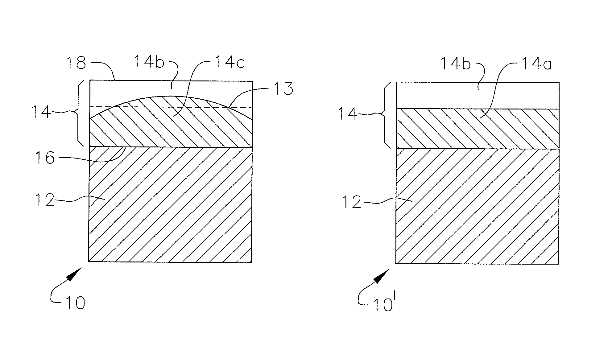
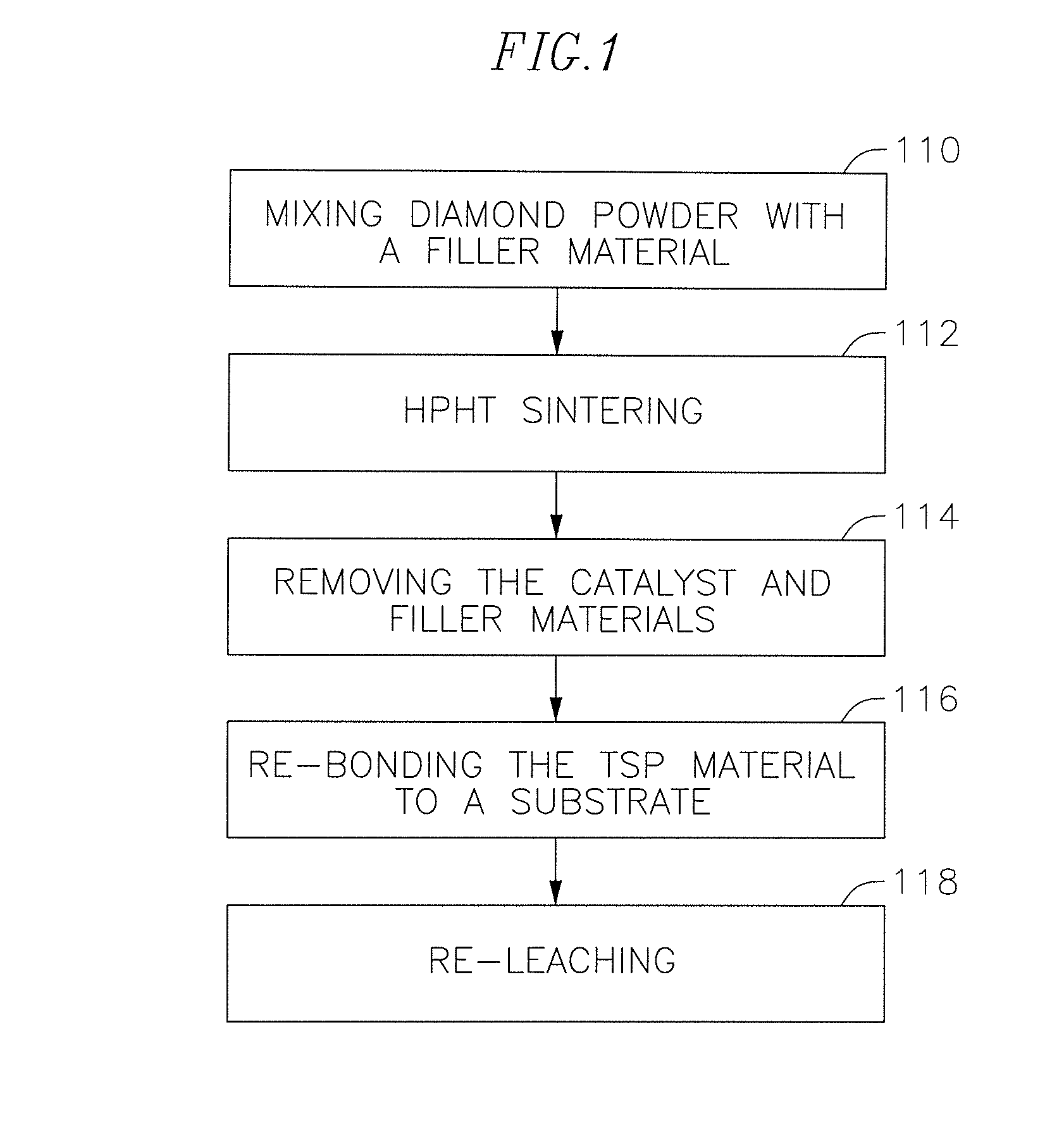
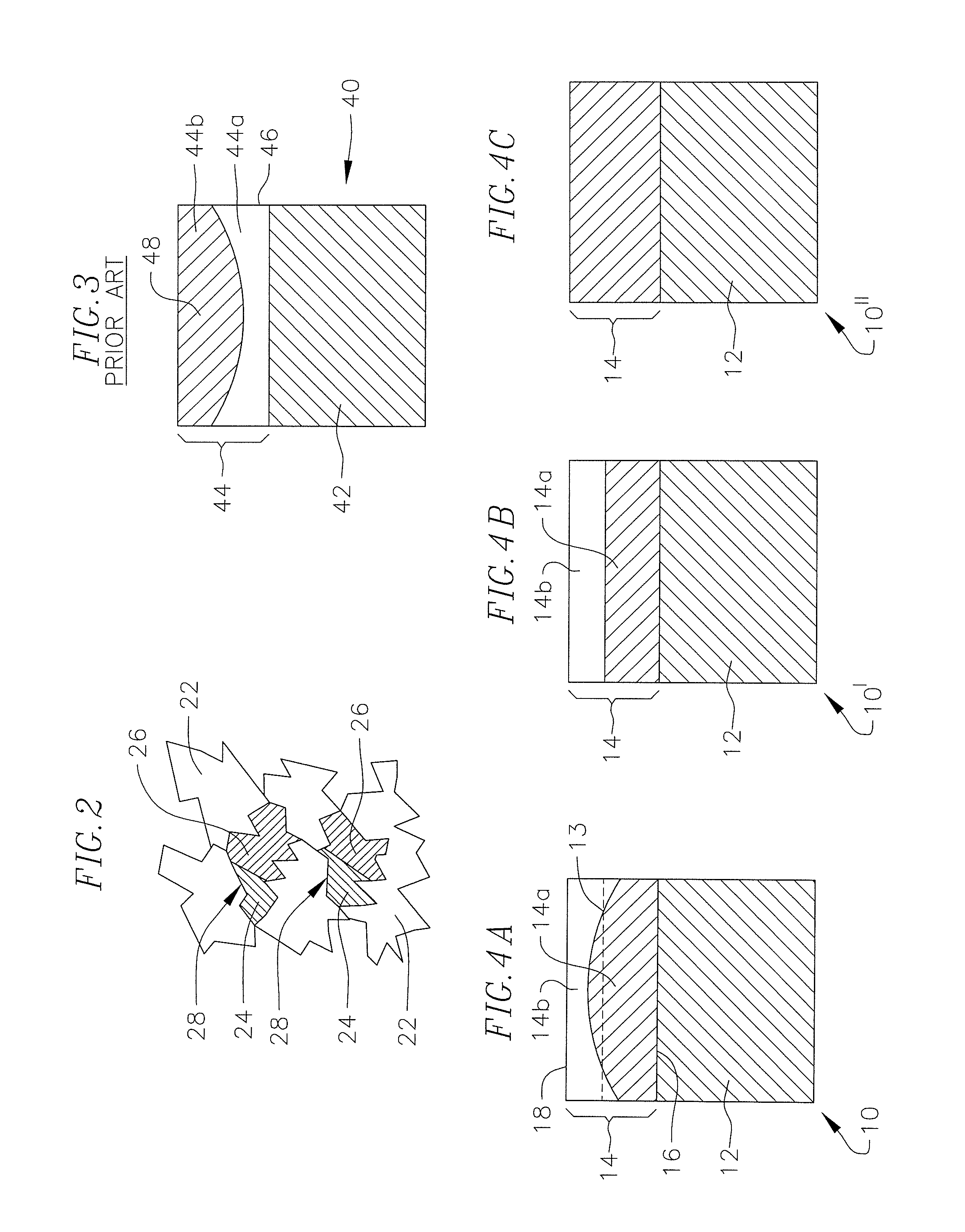
[0020]In an exemplary embodiment, there is provided a method for facilitating infiltration of an infiltrant material into a TSP material during re-bonding of the TSP material to a substrate, by enhancing the porosity of the TSP material near the interface with the substrate. In one embodiment, the method includes mixing a filler material or additive (collectively or individually referred to herein as “filler material”) with a diamond powder mixture prior to HPHT sintering, and then HPHT sintering the diamond powder and filler material mixture to form polycrystalline diamond (PCD). The filler material occupies space in the sintered PCD layer, residing between the bonded diamond crystals. After HPHT sintering, this filler material is removed, such as by leaching, to form a thermally stable product (TSP) with pores between the bonded diamond crystals. The amount and distribution of filler material in the diamond powder is controlled to provide a greater porosity in at least a portion o...


PUM

PropertyMeasurementUnit
porositiesaaaaaaaaaa
differential porosityaaaaaaaaaa

Abstract

A method for facilitating infiltration of an infiltrant material into a TSP material during re-bonding of the TSP material to a substrate, by enhancing the porosity of the TSP material near the interface with the substrate is provided. Cutting elements formed by such method and downhole tools including such cutting elements are also provided.

Description

CROSS-REFERENCE TO RELATED APPLICATION[0001]This application is based upon and claims priority on U.S. Provisional Application No. 61 / 218,382, filed on Jun. 18, 2009, the contents of which are fully incorporated herein by reference.BACKGROUND OF THE INVENTION[0002]Cutting elements, such as shear cutter type cutting elements used in rock bits or other cutting tools, typically have a body (i.e., a substrate) and an ultra hard material. The ultra hard material forms the cutting surface of the cutting element, and the substrate typically attaches the ultra hard material to the cutting tool. The substrate is generally made from tungsten carbide-cobalt (sometimes referred to simply as “cemented tungsten carbide,”“tungsten carbide” or “caarbide”). The ultra hard material layer is a polycrystalline ultra hard material, such as polycrystalline diamond (“PCD”), polycrystalline cubic boron nitride (“PCBN”) or thermally stable product (“TSP”) such as thermally stable polycrystalline diamond. Th...

Claims


Application Information

Patent Timeline
Patent Type & Authority Patents(United States)
IPC IPC(8): E21B10/36E21B10/567
CPCB24D99/005E21B10/36B24D18/0027B24D18/0009E21B10/567E21B10/55C23F1/28C23F1/02
Inventor FAN, GUOJIANGYU, FENGFANG, YIBELNAP, J. DANIELCARIVEAU, PETER T.
Owner SMITH INT INC
Why Eureka
Try Eureka