Compressive optical display and imager

a optical display technology, applied in the field of optical displays and imagers, can solve the problems of large hardware burden on the operational scan range and resolution of the scan mirror optics plus the control electronics of the laser, the image quality is worse for larger screen distances and display image sizes, and the dynamic range of the compressed data optical imager is improved.

Inactive Publication Date: 2014-07-22
RIZA NABEEL +1
View PDF2 Cites 38 Cited by
  • Summary
  • Abstract
  • Description
  • Claims
  • Application Information

AI Technical Summary

Benefits of technology

[0044]The microprocessor based controller can control time modulation of an on/off state of the digital micromirror device micromirrors in the multiple-pixel parallel

Problems solved by technology

A problem with the prior-art laser scanning projection displays is that the farther the distance of the screen from the laser scan optics, the poorer the spatial resolution of the image due to the natural diffraction-based spreading of the Gaussian laser beam that forms the individual pixel/spot in the pixelated display.
As a result there is a tremendous hardware burden on the operational scan range and resolution of the scan mirror optics plus the control electronics for the laser and mirrors.
In prior-art laser scanning displays, as the screen distance increases, the display pixel

Method used


Image

  • Compressive optical display and imager
  • Compressive optical display and imager
  • Compressive optical display and imager

Examples


Embodiment Construction

[0052]Before explaining the disclosed embodiments of the present invention in detail it is to be understood that the invention is not limited in its application to the details of the particular arrangements shown since the invention is capable of other embodiments. Also, the terminology used herein is for the purpose of description and not of limitation.

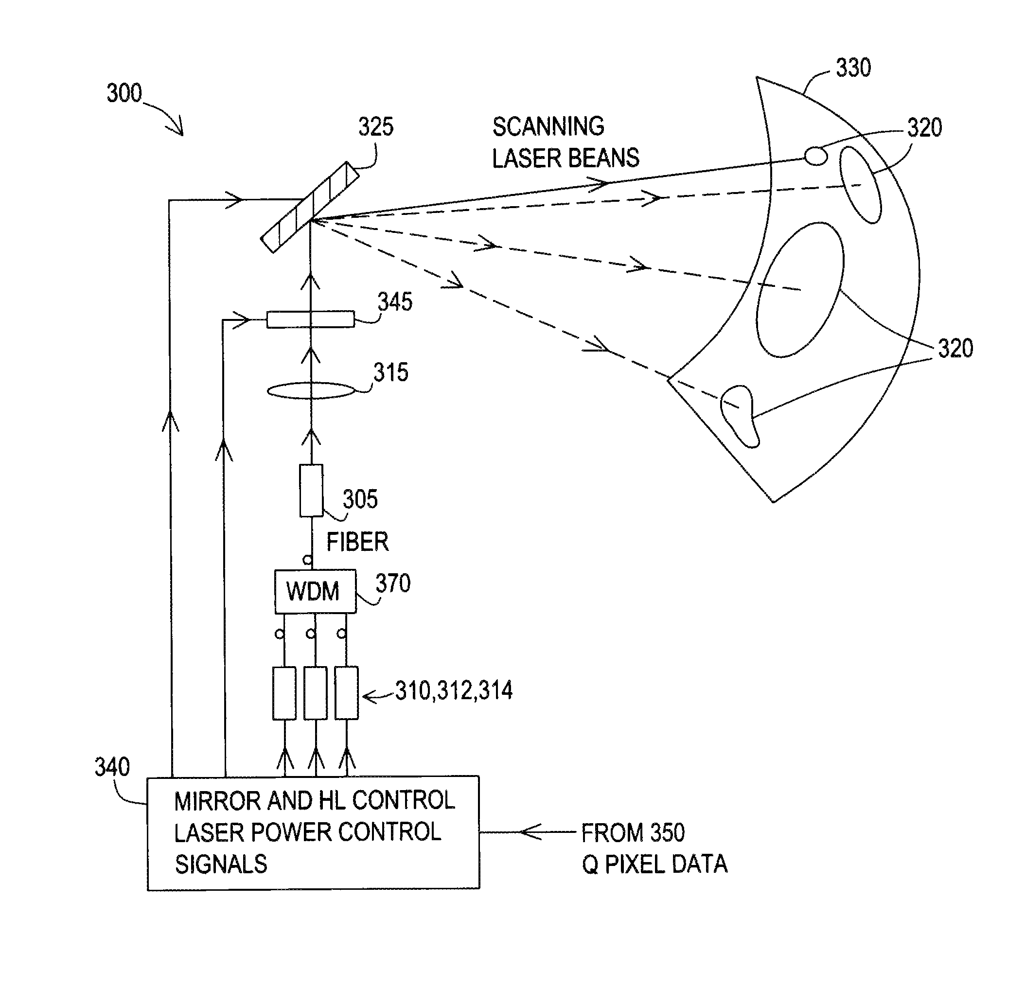
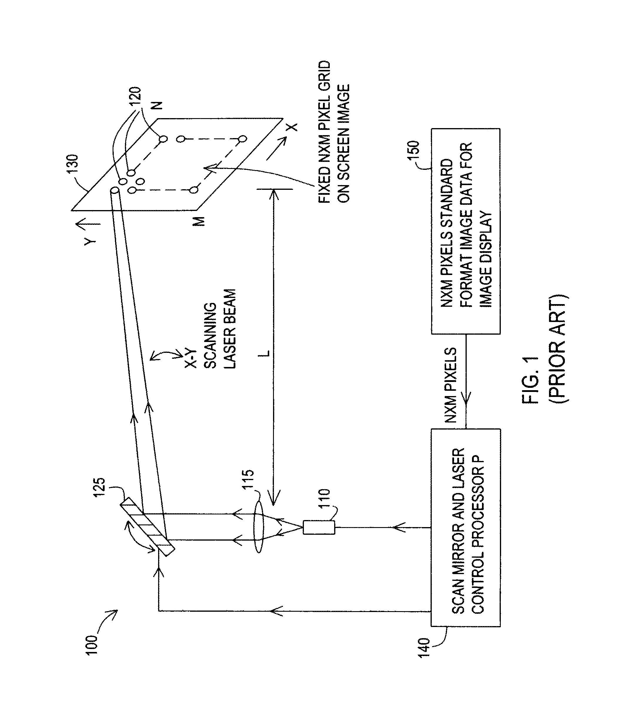
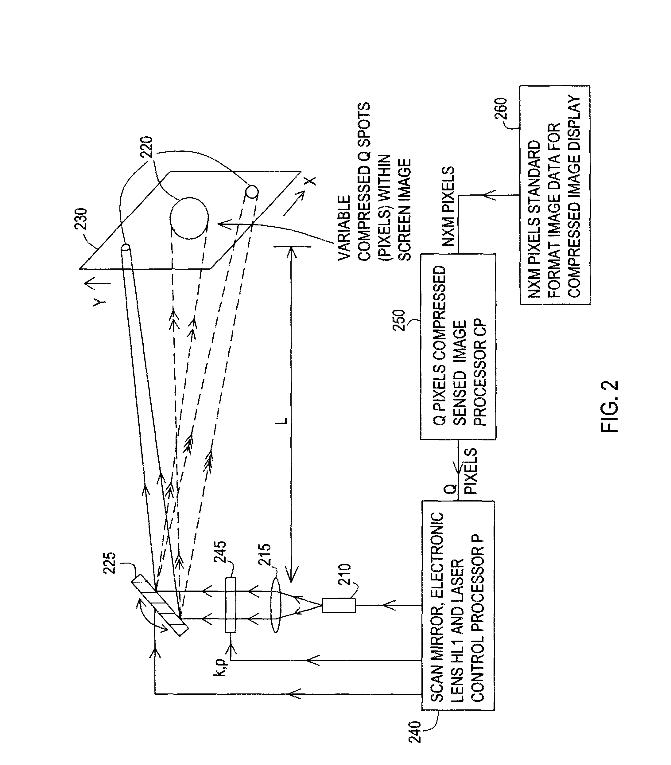
[0053]The following is a list of reference numerals used in the description and the drawings to identify components:[0054]100 2-D laser scanning display[0055]110 laser source[0056]115 lens[0057]120 spot beam[0058]125 x-y scan mirror[0059]130 display screen[0060]140 control processing device[0061]150 compressed image processor[0062]160 image data[0063]200 compressive laser scanning display[0064]210 laser source[0065]215 lens[0066]220 spot beam[0067]225 x-y scan mirror[0068]230 display screen[0069]240 control processing device[0070]245 hybrid electronic lens[0071]250 compressed image processor[0072]260 image data[0073]300 compressive c...


PUM


Abstract

Methods and systems for a compressive optical display and imager using optical scanning and selection and three-dimensional beamforming optics. Standard pixel data can generate a compressed image data set having custom pixel sizes, locations, and intensities. A 3-D beamformer optic adjusts its focus to produce the largest focused beam spot on the display screen corresponding to an image zone compressed pixel. Using scan mirror angular controls, display image space is painted using minimal numbers of laser beam spots whose sizes depend on the compressed sensed image. The imager includes movable reflecting optics to reflect an optical image and controllable imaging optics to pass the reflected optical image toward a digital micromirror that reflects +/−θ optical beams into +/−θ optical beam paths. A controller controls reflecting optics and agile front end imaging optics to receive an electronic image signal corresponding to detected +/−θ optical beams.

Description

FIELD OF THE INVENTION[0001]An optical display that creates an optical image from electronic data while an optical imager creates an electronic image from optical data. In both cases, data is engaged with an optical device called an imager or a display. This invention relates to optical displays and imagers and, in particular, to methods and systems for achieving data compressed display and imager devices.BACKGROUND AND PRIOR ART[0002]Optical displays include laser scanned display fields. A period of rapid growth and change in the display industry has recently given rise to many new display technologies. W. Davis et. al. “MEMS-Based Pico Projector Display,” Proceedings of IEEE / LEOS Optical MEMS & Nanophotonics, Freiburg, Germany, (2008) discloses a unique application of micro electromechanical systems to the area of projection displays. Davis describes a representative example of a DMD-based projection display engine, the digital display engine. The digital display engine is based o...

Claims


Application Information

Patent Timeline
IPC IPC(8): G03B21/28G02B27/10H01S3/10
CPCH01S3/10G02B26/105G02B26/101G03B21/28G02B27/10H04N9/3135
Inventor RIZA, NABEEL, A.
Owner RIZA NABEEL
Why Eureka
Try Eureka