Convection enhanced delivery apparatus, method, and application

a delivery apparatus and enhanced technology, applied in the direction of enzyme stabilisation, peptide/protein ingredients, catheter, etc., can solve the problems of uncontrollable drug delivery, unfavorable tissue disturbance, and difficulty in controlling the distribution of infused molecules, so as to reduce the disturbance of tissue, reduce backflow or reflux, and reduce the cross-sectional area.

Active Publication Date: 2014-07-29
CORNELL UNIVERSITY +1
View PDF21 Cites 15 Cited by
  • Summary
  • Abstract
  • Description
  • Claims
  • Application Information

AI Technical Summary

Benefits of technology

[0018]By way of an illustrative, non-limiting example, a microfabricated device according to an embodiment of the invention is used for CED of drugs to treat disorders of the brain and other neural tissue. When used in the brain, the device circumvents the blood-brain barrier (BBB) by infusing drugs under positive pressure directly into tissue. According to an illustrative aspect, the microfabricated device comprises a silicon shank that contains one or more parylene channels. The silicon shank provides rigidity for inserting the device into the brain; the one or more parylene channels conduct drug-containing fluid(s) along the shank under pressure and release the fluid(s) through an open port in the shank for dispersal into the brain. The device is an improvement over conventional stainless steel needle-type catheters that are currently used for CED of drugs. Enumerated exemplary advantages of the device include: 1) a smaller cross-sectional area compared with conventional needles used in CED; 2) less disturbance to tissue when inserted into the brain than conventional needles; 3) the elimination of backflow or reflux along the outside of the inserted part, which in turn, permits higher rates of drug delivery in the device compared with conventional needles; 4) minimal or no occlusion of the channel during insertion into the brain; 5) multiple parylene channels can be fabricated into the silicon shank, each conducting a distinct fluid (drug), which allows simultaneous, sequential, or programmed delivery of multiple agents; 6) the device has the potential to serve simultaneously as a drug delivery system and as a sensor-equipped probe to measure local tissue characteristics such as, but not limited to, pressure, pH, ion-specific concentrations, location, and other parameters.

Problems solved by technology

However, it can be difficult to control the distribution of infused molecules when characteristics of the tissue vary within the treatment region, such as in heterogenous tumors and near white matter tracts in the brain.
Clinical trials for treating brain tumors have reported similar problems in tracking and predicting the distribution of infused chemotherapy agents.
Backflow reduces control over drug delivery because infused solutions can flow out of the brain or into highly permeable white matter tracts surrounding the infusion site.
Another problem encountered with needles is an unexpectedly large pressure at the needle tip at the start of an infusion.
There are questions, however, about the reliability of such measures for studies of release and uptake of neuronal glutamate.
Poor spatial resolution and slow time resolution attributed to the technique may result in inadequate sampling of neurotransmitters with fast kinetics like L-glutamate.
However, the microelectrodes previously reported have suffered from problems associated with the size of the recording microelectrodes, the microelectrode response time and the lack of ability to mass produce the microelectrodes.
However, transport of particles through the extracellular space of tissues is hindered by the large size of nanoparticles (10-100 nm), which are much larger than small molecule drugs or therapeutic proteins that more easily penetrate the brain extracellular matrix (ECM).
Other factors also may limit the extent of particle penetration in the brain.

Method used


Image

  • Convection enhanced delivery apparatus, method, and application
  • Convection enhanced delivery apparatus, method, and application
  • Convection enhanced delivery apparatus, method, and application

Examples


Embodiment Construction

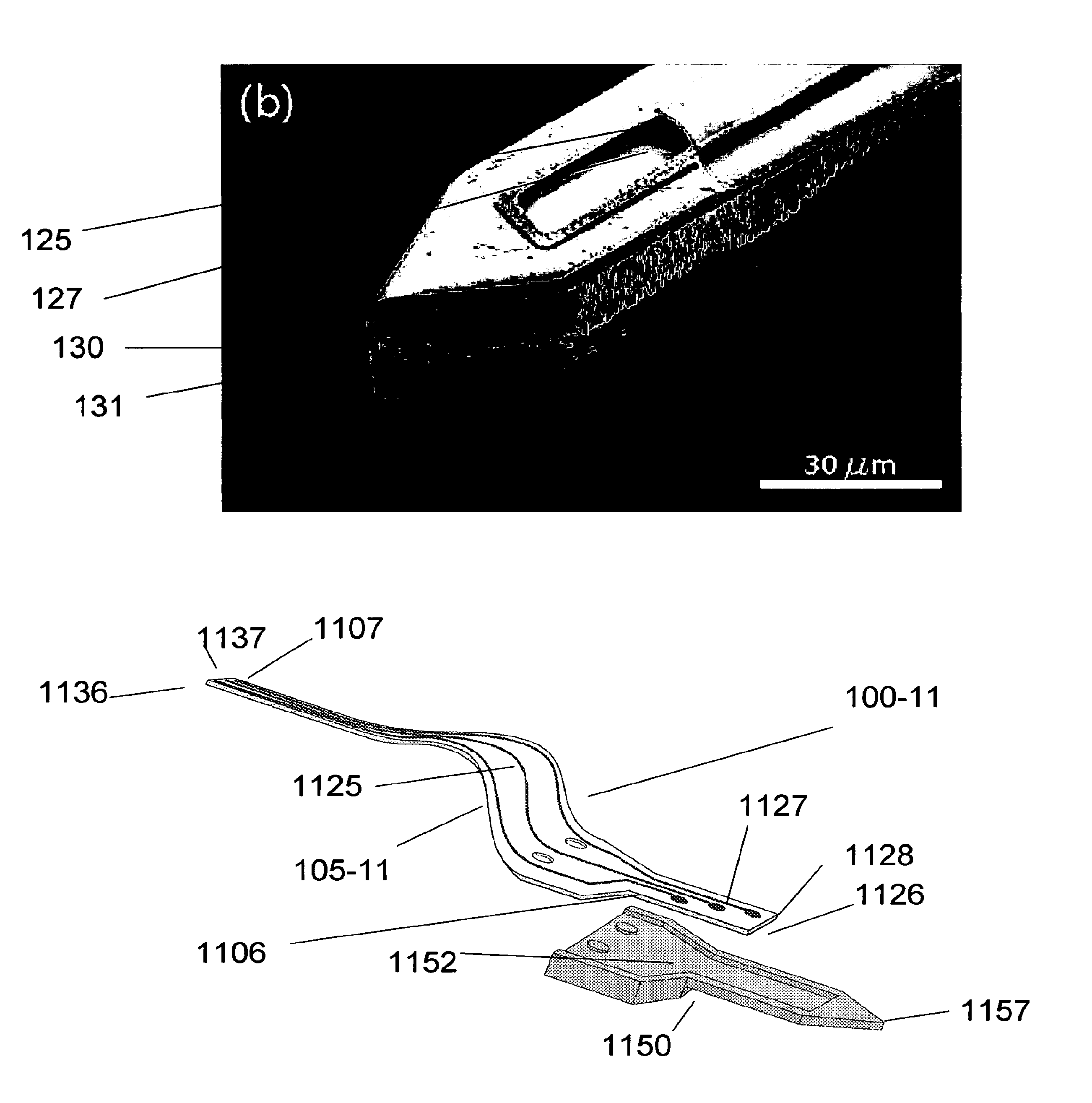
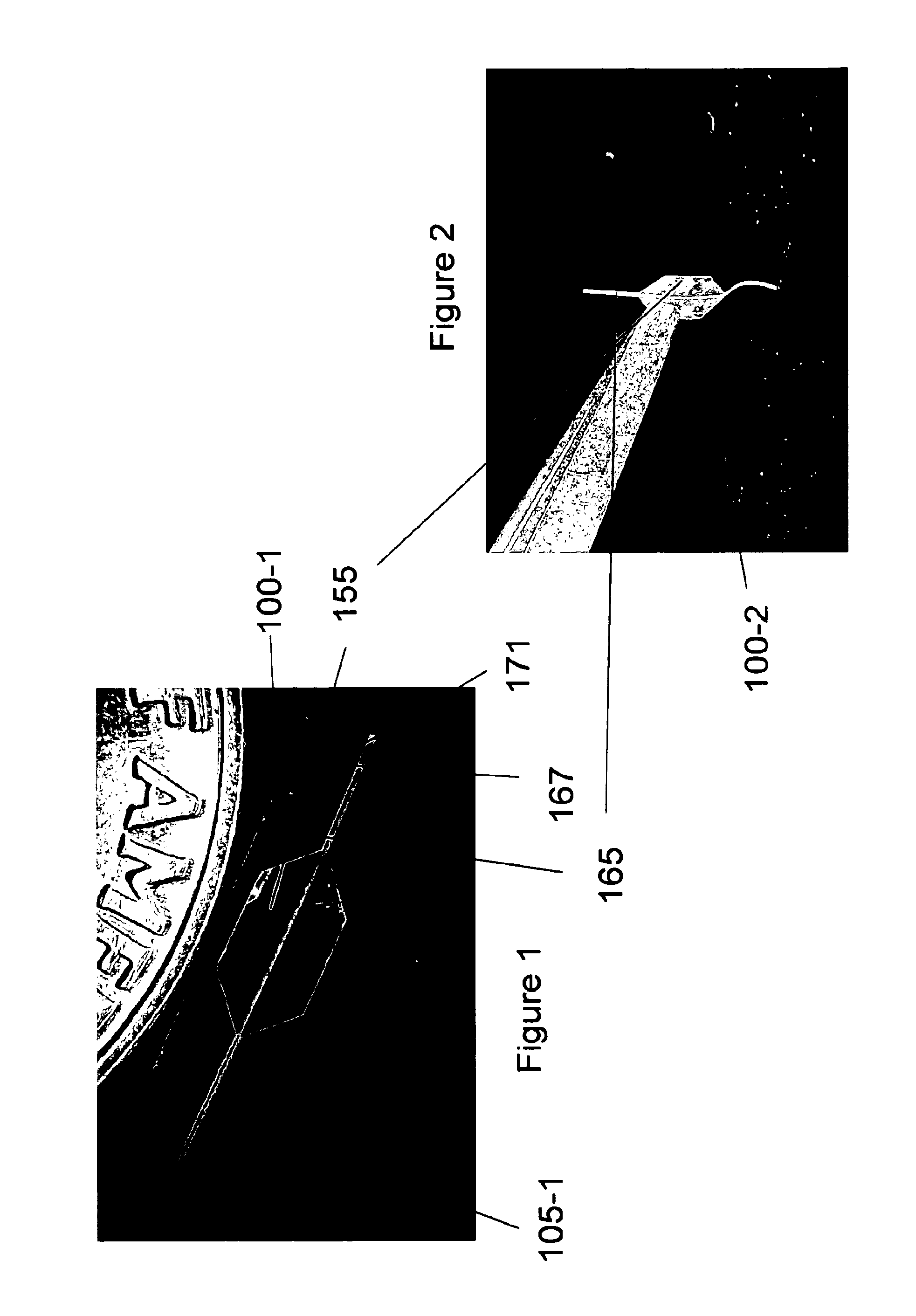
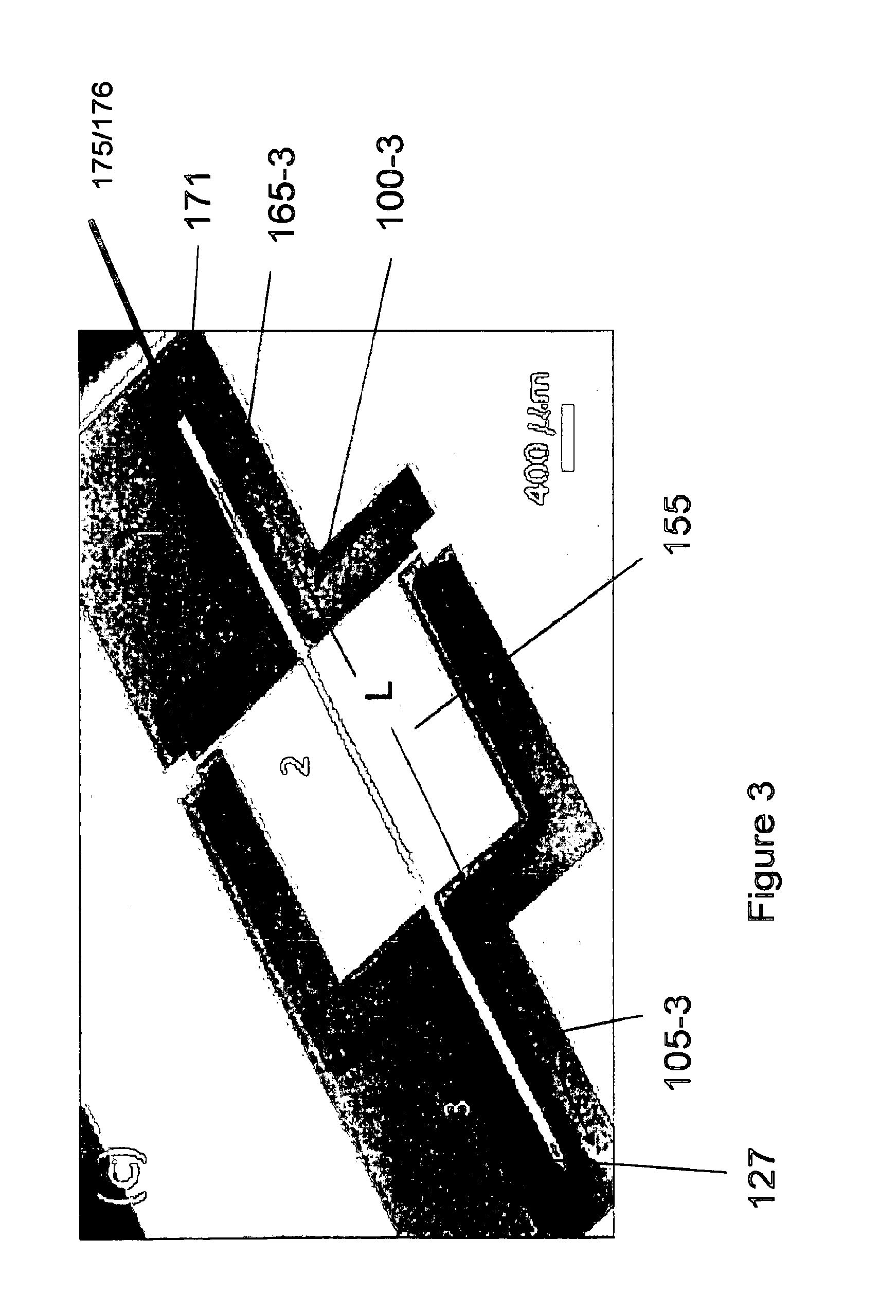
[0017]An embodiment of the invention is directed to a microfabricated, silicon-based CED device. The device comprises a silicon shank portion, at least one individual parylene channel disposed along at least a part of an entire length of the shank, wherein the channel has one or more dimensioned fluid exit ports disposed at one or more respective locations of the channel and a fluid (drug) input opening. The fluid input opening may be configured or adapted to be connected to a fluid reservoir and / or a pump and / or a meter and / or a valve or other suitable control device(s) or apparatus that supplies and / or delivers fluid (e.g., a drug) to the microfabricated device. According to an aspect, the device includes a handle to aid in the manipulation of the device. A distal end of the device may be pointed or otherwise appropriately shaped to aid in its penetration of tissue or other anatomical structure. According to an aspect, the one or more individual parylene channels and their associa...


PUM

PropertyMeasurementUnit
lengthaaaaaaaaaa
lengthaaaaaaaaaa
lengthaaaaaaaaaa

Abstract

An embodiment of the invention is directed to a microfabricated, silicon-based, Convection Enhanced Delivery (CED) device. The device comprises a silicon shank portion, at least one individual parylene channel disposed along at least a part of an entire length of the shank, wherein the channel has one or more dimensioned fluid exit ports disposed at one or more respective locations of the channel and a fluid (drug) input opening. The fluid input opening may be configured or adapted to be connected to a fluid reservoir and / or a pump and / or a meter and / or a valve or other suitable control device(s) or apparatus that supplies and / or delivers fluid (eg, a drug) to the microfabricated device. The device may have multiple channels disposed side by side or in different surfaces of the device.

Description

FEDERALLY SPONSORED RESEARCH[0001]Certain embodiments and aspects of the disclosed invention were made with government support under Contract No. NS-045236 awarded by the National Institutes of Health. The work reported herein was performed in part at the Cornell NanoScale Facility, a member of the National Nanotechnology Infrastructure Network, which is supported by the National Science Foundation Grant ECS 03-35765. The United States government may have certain rights in the invention.RELATED APPLICATION DATA[0002]This application claims priority to U.S. provisional application Ser. No. 60 / 889,555 entitled Convection Enhanced Delivery Apparatus, Method, and Application filed on Feb. 13, 2007 and incorporated herein by reference in its entirety.BACKGROUND[0003]1. Field of the Invention[0004]Embodiments of the invention pertain generally to the field of Convection Enhanced Delivery (CED) of therapeutic and / or diagnostic agents (hereinafter referred to as, but not limited per se to, ...

Claims


Application Information

Patent Timeline
Patent Type & Authority Patents(United States)
IPC IPC(8): A61M5/00
CPCA61K38/47C12Y302/01035A61M2037/0023A61M37/00C12Y302/01A61M2037/003A61M37/0015A61M2210/0693A61M5/1408
Inventor OLBRICHT, WILLIAM L.NEEVES, KEITH B.FOLEY, CONORMATTEWS, RUSSELL T.SALTZMAN, W. MARKSAWYER, ANDREW
Owner CORNELL UNIVERSITY
Why Eureka
Try Eureka