
Mobile station and methods for diagnosing and modeling site specific full-scale effluent treatment facility requirements

a mobile station and effluent treatment technology, applied in water/sewage treatment by ion exchange, process and machine control, analogue computers for distribution networks, etc., can solve the problems of not all effluent treatment requires the same technology, affects ongoing operations financially and in terms of operational continuity, and the mechanism is limited in application and adaptability. , to achieve the effect of improving operational continuity and reducing financial risks

Inactive Publication Date: 2014-07-29
ROCKWATER RESOURCE
View PDF44 Cites 12 Cited by
  • Summary
  • Abstract
  • Description
  • Claims
  • Application Information

AI Technical Summary

Benefits of technology

This approach allows for accurate, cost-effective, and adaptable evaluation of effluent treatment needs, reducing financial risk and improving operational continuity by providing real-time data for full-scale plant operation, size, and cost estimation.

Problems solved by technology

Such facilities typically represent a significant investment by the business / community, and the performance of the facility (or failure thereof) can seriously impact ongoing operations financially and in terms of operational continuity.
Moreover, not all effluent treatment requires the same technologies.
Given the expense of full-scale water treatment technology deployment, it would be foolish to plan and build a facility with treatment stages not needed to address the particular problems to be encountered and outcomes desired at the particular treatment site.
Such mechanisms tend to be limited both in application and adaptability.
Presently known pilot test tools are often quite limited in scope and are typically based initially on laboratory / bench scale tests, with ongoing pilot design refinement essentially requiring pilot plant redesign for each iteration.
Higher levels of pilot refinement are thus mostly limited by cost considerations.

Method used


Image

  • Mobile station and methods for diagnosing and modeling site specific full-scale effluent treatment facility requirements
  • Mobile station and methods for diagnosing and modeling site specific full-scale effluent treatment facility requirements
  • Mobile station and methods for diagnosing and modeling site specific full-scale effluent treatment facility requirements

Examples


embodiment 1601

[0165]The higher air and / or plasma-gas pressure provides adequate sealing action between the active membrane side and the coiled feed path. The thickness of the coiled feed path in relation to membrane sleeve 1611 diameter is in the range of 1:5 to 1:500. Coil feed path length in relation to sleeve 1611 length is in the range of 2:1 to 200:1. As maybe appreciated membrane cost savings are realized while ease of membrane exchange or replacement and large membrane area are provided. Visual inspection of bubble generation is allowed through the clear outer housing body enabling better bubble control. Embodiment 1601 maximizes efficiency due to integrated non-plugging inline mixing (no added static inline mixing device is needed) and compact design.

[0166]FIG. 17 shows a second embodiment 1701 of membrane aeration apparatus 803 of second pre-treatment suite 413 (similar elements retaining numbering from prior occurrence). In this second ODE variation, tubular or capillar membrane bundles...

third embodiment

[0177]While shown utilizing the emitter 1803 of the third embodiment, this embodiment can be employed also with photo (UV) initiated air ionization technology. If radioactive initiated air ionization is employed, the positively charged α-particles will deflect towards the negatively charged electrical field. The frequency controlled alternating deflection of the α-particles takes place primarily within the upper portion of the ionization chamber. This alternating deflection provides additional collision potentials with the continual incoming large number of neutral air molecules, thus slowing the recombination of positive and negative ion pairs prior to exposure to the contaminated effluent.

[0178]The alternating current flow provides an enhanced distribution environment for the diffusively aerated ionized air / gas for balancing the surface charge of particles in the feed water solution thus removing or reducing the electrical repulsive charge on the particles. This hydrodynamic mixin...

first embodiment

[0266]In accordance with another aspect of this invention, a high frequency membrane separation apparatus and method utilizable with membrane systems of this invention is shown in FIGS. 33a and 33b. This invention relates to apparatus and methods for fluid filtering utilizing membrane separation (for example nanofiltration and / or reverse osmosis filtration) that combines vibratory shear techniques with adjustable crossflow techniques. This and further embodiments of the high frequency membrane separation apparatus and methods (set forth hereinafter) are particularly well adapted to treatment stages 419, 423, 429 and / or 433 when membrane treatment options are applied (generically referred to hereinafter as membrane treatment systems).

[0267]High frequency membrane separation herein refers to vibrating, oscillatory motion of the membrane support structure. Vibration direction is perpendicular to the floor of station 101 for gravity assisted membrane separation systems. The vibration cu...


PUM

PropertyMeasurementUnit
areaaaaaaaaaaa
heightaaaaaaaaaa
generator poweraaaaaaaaaa

Abstract

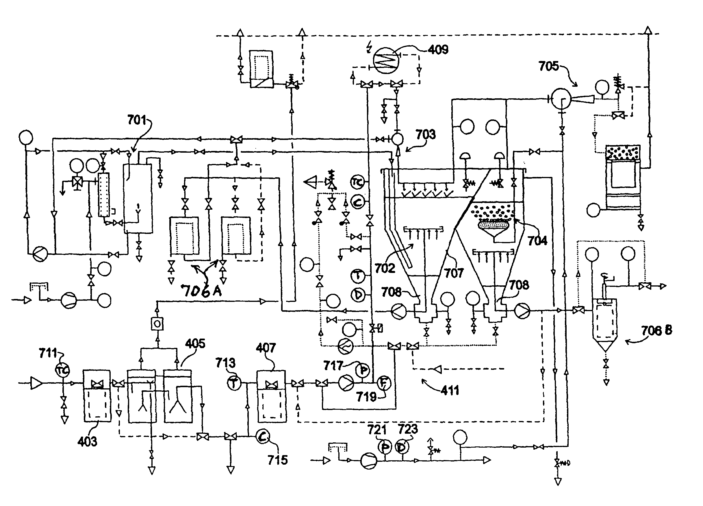
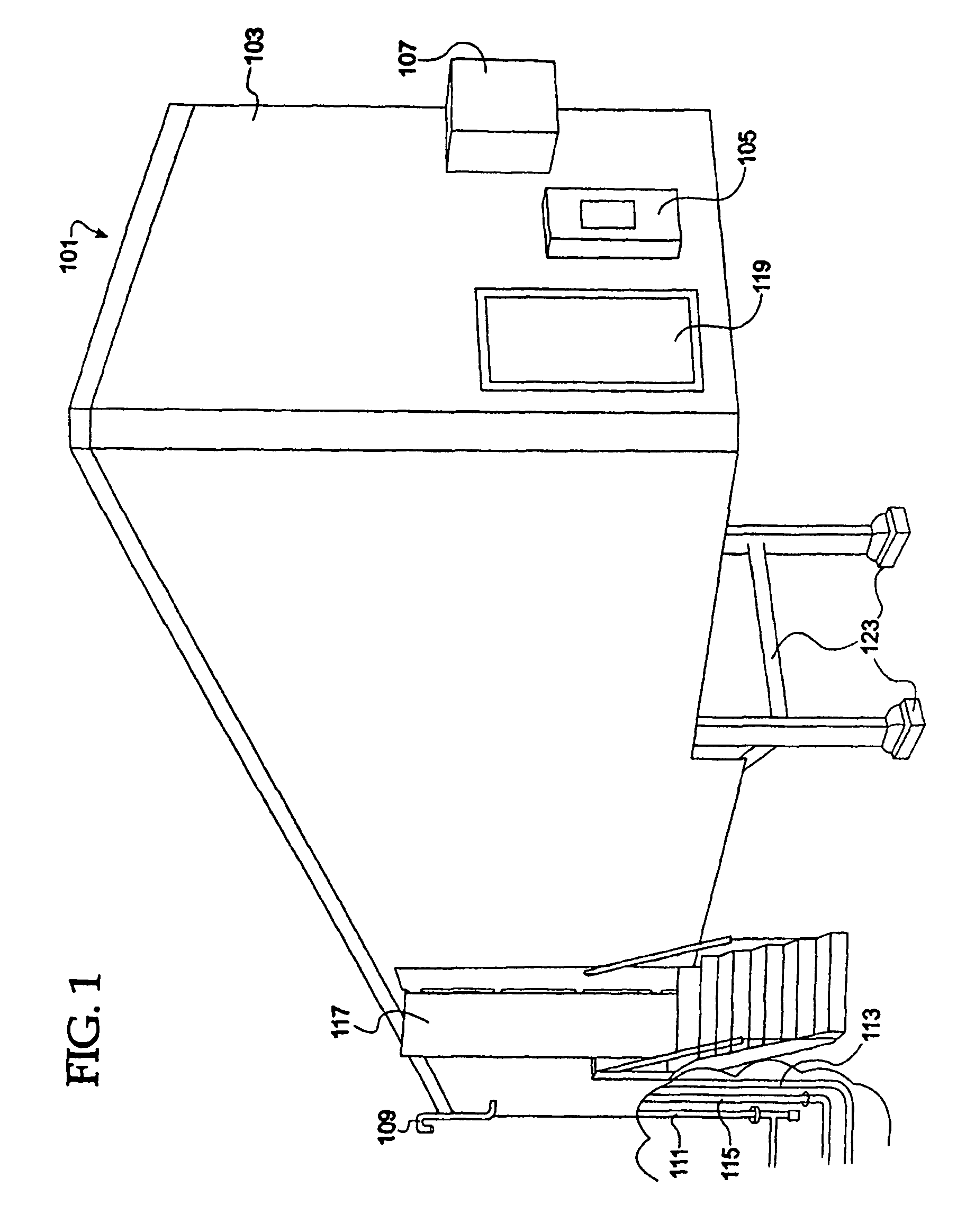
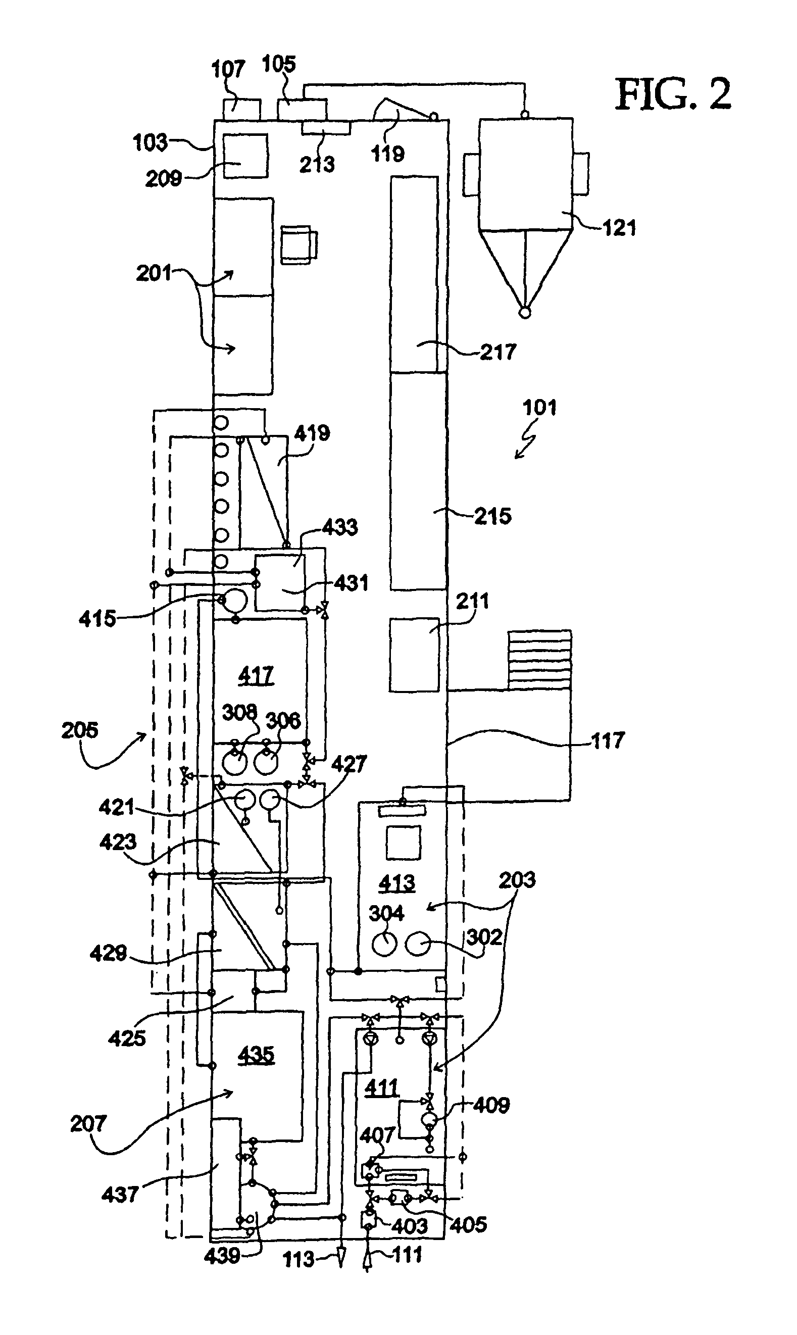
A mobile station and methods are disclosed for diagnosing and modeling site specific effluent treatment facility requirements to arrive at a treatment regimen and / or proposed commercial plant model idealized for the particular water / site requirements. The station includes a mobile platform having power intake, effluent intake and fluid outflow facilities and first and second suites of selectably actuatable effluent pre-treatment apparatus. An effluent polishing treatment array is housed at the station and includes at least one of nanofiltration, reverse osmosis and ion-exchange stages. A suite of selectively actuatable post-treatment apparatus is housed at the station. Controls are connected at the station for process control, monitoring and data accumulation. A plurality of improved water treatment technologies is also disclosed. The modeling methods include steps for analyzing raw effluent to be treated, providing a field of raw effluent condition entry values and a field of treated effluent condition goals entry values, and utilizing said fields to determine an initial treatment model including a selection of, and use parameters for, treatment technologies from the plurality of down-scaled treatment technologies at the facility, the model dynamically and continuously modifiable during treatment modeling.

Description

RELATED APPLICATION[0001]This application is a Divisional and Continuation-in-part application of U.S. patent application Ser. No. 11 / 888,512 filed on Aug. 1, 2007 now abandoned by Wiemers et al. and entitled “MOBILE STATION FOR DIAGNOSING AND MODELING SITE SPECIFIC EFFLUENT TREATMENT FACILITY REQUIREMENTS”.FIELD OF THE INVENTION[0002]This invention relates to effluent treatment, and, more particularly, relates to facilities and methods for modeling and evaluating particularized water treatment and water treatment facility requirements, regimens and costs.BACKGROUND OF THE INVENTION[0003]Most industrial and municipal processes require water treatment facilities to treat effluents returned to the environment. Such facilities typically represent a significant investment by the business / community, and the performance of the facility (or failure thereof) can seriously impact ongoing operations financially and in terms of operational continuity.[0004]Moreover, not all effluent treatment ...

Claims


Application Information

Patent Timeline
Patent Type & Authority Patents(United States)
IPC IPC(8): C02F9/02G05B13/04C02F9/00
CPCB01D61/027C02F1/441C02F1/42C02F2001/007C02F1/66C02F1/442C02F1/463C02F1/20C02F1/44C02F1/444C02F1/008B01D61/022C02F2201/008C02F1/52C02F1/38C02F2201/4612C02F1/32C02F2209/006C02F3/082C02F9/00C02F1/28C02F2209/00C02F2209/008C02F2201/461B01D61/025Y02W10/15Y02W10/10B01D61/029
Inventor WIEMERS, REGINALD A.KOHLHEB, ROBERTKHALILI, BARDIA B.LIPOVSZKI, GYORGYZAHN, PETER H.
Owner ROCKWATER RESOURCE
Learn More