Method and digital circuit for recovering a clock and data from an input signal using a digital frequency detection

a digital frequency detection and clock and data technology, applied in the field of method and digital circuit for recovering a clock and data from an input signal, can solve the problems of more overhead, slow circuit response time, and degradation of clock and data recovery circuit performance, and achieve the effect of reducing loading

Active Publication Date: 2014-08-05
QUALCOMM INC
View PDF21 Cites 6 Cited by
  • Summary
  • Abstract
  • Description
  • Claims
  • Application Information

AI Technical Summary

Benefits of technology

[0004]A clock and data recover (CDR) circuit having sampler, a digital phase detector, and a digital frequency detection circuit may be used, where the sampler receives an input signal and provides sequential samples to a digital phase detector. The digital phase detector, such as a bang-bang phase detector, detects transitions between the sequential samples and provides transition data to the digital frequency detection circuit. The digital frequency detection circuit stores the transition data and monitors the transition data to determine whether a sampling rate of the sampler needs to be increased or decreased for the CDR circuit to lock to the frequency of the input signal. The output signal from the digital frequency detection circuit results in the generation of a control signal that adjusts a frequency of the sampling clock that controls the sampling rate.
[0005]Alternatively, the digital frequency detection circuit may be configured to receive samples from a de-serializer instead of receiving transition data from the digital phase detector. For example, the sampler may provide the sequential samples to a de-serializer that packages the sequentially received sequential samples into a number of parallel samples. The de-serializer has the effect of reducing the speed required by the digital frequency detection circuit. The digital frequency detection circuit detects transitions between the samples received from the de-serializer and stores the transition data. The digital frequency detection circuit monitors the stored transition data to determine whether a sampling rate of the sampler should be increased or decreased for the CDR circuit to lock to the frequency of the input signal. The output signal from the digital frequency detection circuit results in the generation of a control signal that adjusts the frequency of a sampling clock that controls the sampling rate of the sampler. The de-serializer receives the sequential samples serially (e.g., a single sample is provided to the de-serializer each clock cycle) and provides N (an integer greater than one) samples in parallel after the N samples have been received at the de-serializer, resulting in a parallel output to the digital frequency detection circuit every Nth clock cycle. Therefore, the clock speed requirements for the digital frequency detection circuit are reduced (e.g., the clock speed requirements may be reduced by a factor of N).
[0007]In another particular embodiment, a method of recovering a clock and data from an input signal includes reducing a sampling rate of a received signal in response to a predetermined number of sequential samples of the received signal having a same value. Information related to transitions between sample values of the received signal is received from a digital phase detector.
[0010]One particular advantage provided by at least one of the disclosed embodiments is a reduction in loading at an input where the CDR circuit receives the input signal and at a clock output of the CDR circuit.

Problems solved by technology

However, the addition of the frequency detection circuit to the input node and the clock node may degrade the performance of the clock and data recovery circuit.
For example, the addition of the frequency detection circuit at the input and clock nodes increases the loading at those nodes resulting in more overhead and slower circuit response times. Further, the increased loading at the nodes changes the behavior at the nodes, changes the dynamics of a clock and data recovery circuit, changes the sampling points of the input signal, and adds to the complexity of the circuit design.

Method used


Image

  • Method and digital circuit for recovering a clock and data from an input signal using a digital frequency detection
  • Method and digital circuit for recovering a clock and data from an input signal using a digital frequency detection
  • Method and digital circuit for recovering a clock and data from an input signal using a digital frequency detection

Examples


Embodiment Construction

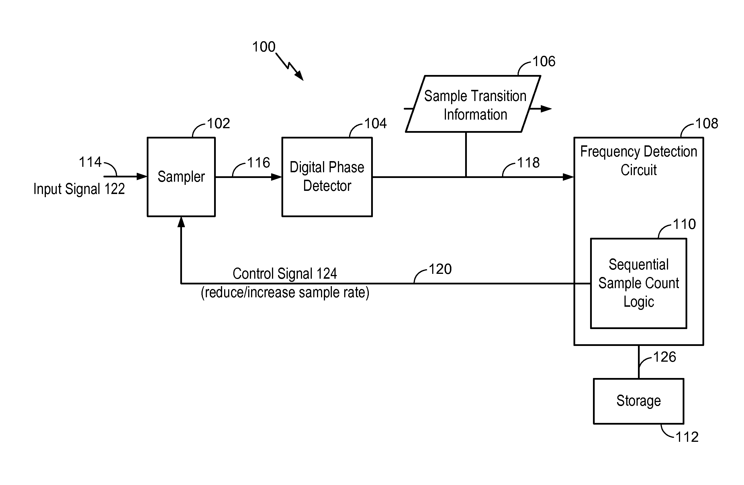
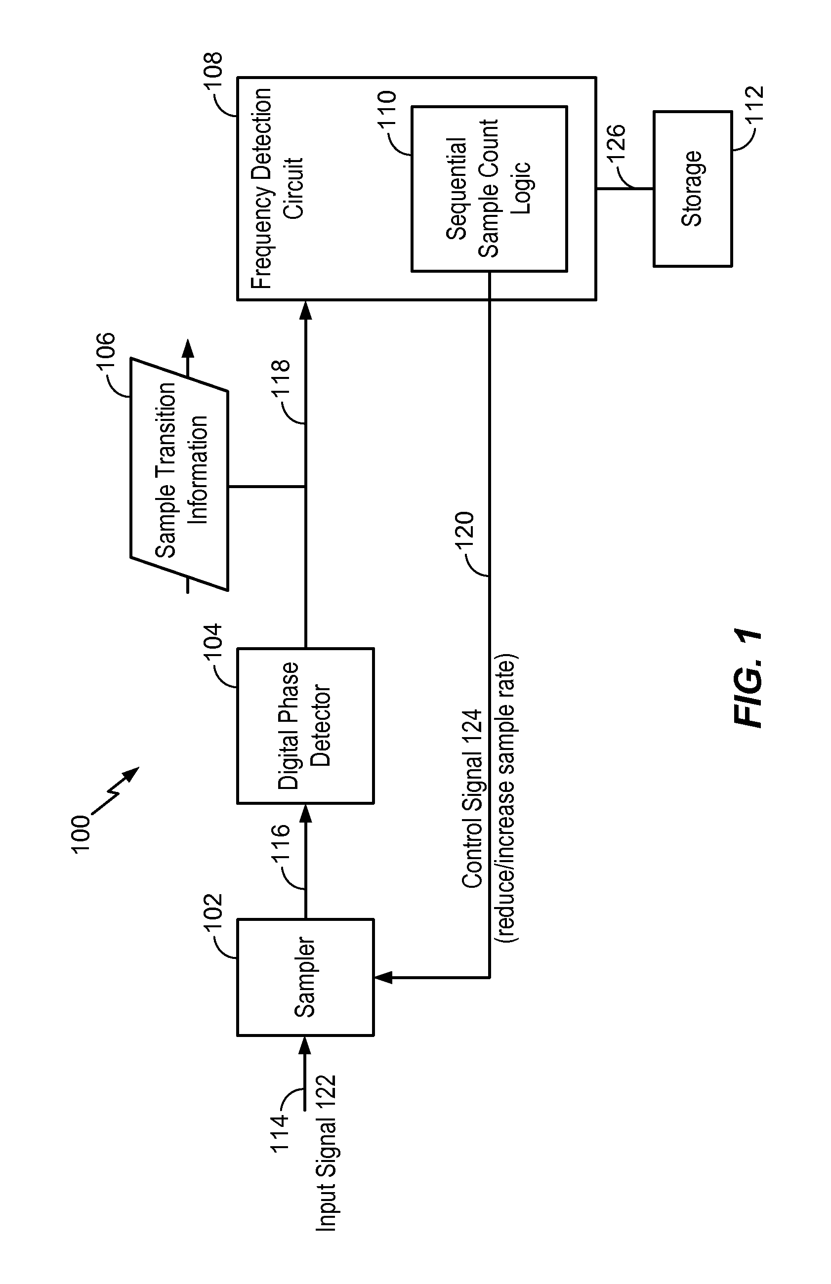
[0022]A clock and data recovery (CDR) circuit may be employed at a receiver to recover a clock signal and data from a received input signal, where the received input signal does not include a reference clock signal. For example, the received input signal may be a non-return to zero (NRZ) input signal that does not include a reference clock signal and that may be encoded in accordance with a standard, such as an 8b / 10b standard. The pull-in time and locking time of the received input signal at the receiver affects the speed of the receiver. The pull-in time and the locking time may be improved by including a digital frequency detection circuit within the CDR circuit.

[0023]The digital frequency detection circuit may utilize transition timing information generated from sequentially sampled values at a digital phase detector to determine whether the sampling rate of the input signal needs to be adjusted in order to lock on to the frequency of the input signal. The digital frequency dete...


PUM


Abstract

In a particular embodiment, a digital circuit includes a frequency detection circuit operative to compare information related to transitions between sequential samples of a received signal. The frequency detection circuit is further operative to generate a control signal to reduce a sampling rate of the received signal in response to a predetermined number of the sequential samples having a same value. The digital circuit also includes a digital phase detector operative to provide the information related to the transitions between sequential samples to the frequency detection circuit.

Description

I. FIELD[0001]The present disclosure is generally related to a method and digital circuit for recovering a clock and data from an input signal using low overhead digital frequency detection.II. DESCRIPTION OF RELATED ART[0002]Advances in technology have resulted in smaller and more powerful computing devices. For example, there currently exist a variety of portable personal computing devices, including wireless computing devices, such as portable wireless telephones, personal digital assistants (PDAs), and paging devices that are small, lightweight, and easily carried by users. More specifically, portable wireless telephones, such as cellular telephones and Internet Protocol (IP) telephones, can communicate voice and data packets over wireless networks. Many such wireless telephones incorporate additional devices to provide enhanced functionality for end users. For example, a wireless telephone can also include a digital still camera, a digital video camera, a digital recorder, and ...

Claims


Application Information

Patent Timeline
Patent Type & Authority Patents(United States)
IPC IPC(8): H04L7/00
CPCH04L7/033H04L7/0337H03L7/113
Inventor KONG, XIAOHUAZHU, ZHIDANG, NAM V.SOWLATI, TIRDAD
Owner QUALCOMM INC
Why Eureka
Try Eureka