Developing member, process cartridge, and electrophotographic apparatus

a technology of electrophotography and process cartridges, applied in the direction of electrically conductive paints, electrographic processes, instruments, etc., can solve the problems of generating trace of electrical breakdown and leakage of aggregates, and achieves high electroconductivity, excels in filming resistance, and excels in leak resistance.

Active Publication Date: 2014-08-05
CANON KK
View PDF8 Cites 36 Cited by
  • Summary
  • Abstract
  • Description
  • Claims
  • Application Information

AI Technical Summary

Benefits of technology

[0012]In addition, an electrophotographic process in which a high voltage is applied to a developing member has been supposed for higher quality of an electrophotographic image. The developing member used in such an electrophotographic process needs to have a surface layer which has appropriate electroconductivity as well as excellent leak resistance, that is, which does not cause electric leak to occur even when a high voltage (for example, about DC 500 V) is applied. In the case where electric leak occurs from the surface layer, a trace of electrical breakdown is generated on the surface layer, and ultimately, transversely streaked density unevenness due to the leak may occur on the electrophotographic image. In the case where an electronically conductive filler typified by carbon black is dispersed into a binder resin in the surface layer to impart electroconductivity to the surface layer, if the dispersion of the electronically conductive filler into the binder resin is insufficient, aggregates of the electronically conductive filler are formed in the surface layer and leak may occur in the aggregates.
[0014]Furthermore, the present invention is directed to providing an electrophotographic apparatus capable of stably outputting a high-quality electrophotographic image, and a process cartridge used for the electrophotographic apparatus.
[0025]According to the present invention, a high-quality developing member can be provided which is flexible and excels in filming resistance and which has high electroconductivity and further excels in leak resistance by forming a surface layer containing a urethane resin and an acrylic resin having a specific structural unit.
[0026]Moreover, according to the present invention, a process cartridge and an electrophotographic apparatus can be obtained which can stably provide a high-quality electrophotographic image.

Problems solved by technology

In the case where electric leak occurs from the surface layer, a trace of electrical breakdown is generated on the surface layer, and ultimately, transversely streaked density unevenness due to the leak may occur on the electrophotographic image.
In the case where an electronically conductive filler typified by carbon black is dispersed into a binder resin in the surface layer to impart electroconductivity to the surface layer, if the dispersion of the electronically conductive filler into the binder resin is insufficient, aggregates of the electronically conductive filler are formed in the surface layer and leak may occur in the aggregates.

Method used


Image

  • Developing member, process cartridge, and electrophotographic apparatus
  • Developing member, process cartridge, and electrophotographic apparatus
  • Developing member, process cartridge, and electrophotographic apparatus

Examples


example 1

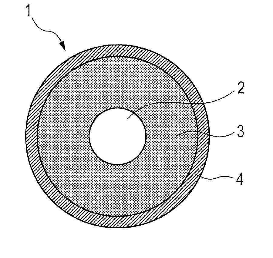
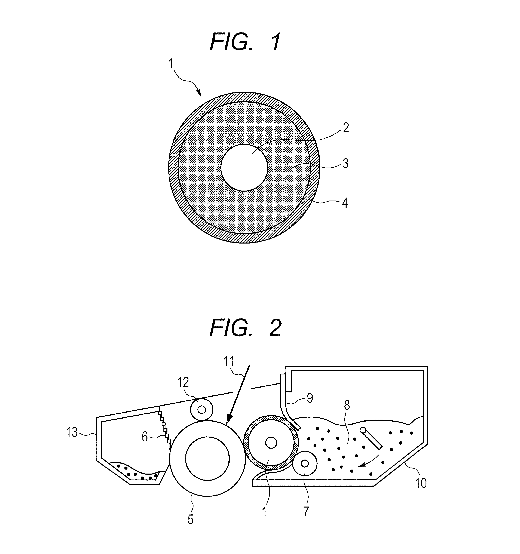
[0161]Hereinafter, a manufacturing method of the developing roller according to the present invention will be described.

[0162]As a material for the surface layer 4, with respect to 100.0 parts by mass of Polyol A-1, 109.0 parts by mass of Isocyanate Group-Terminated Prepolymer B-1, 5.3 parts by mass of Acrylic Resin C-1, and 32.0 parts by mass of gas black (trade name, Color Black S-160; manufactured by Evonik Degussa Japan Co., Ltd.) having a primary particle diameter of 20 nm were stirred and mixed.

[0163]Next, after the mixture was dissolved in methylethylketone (hereinafter, abbreviated to “MEK”) such that the total solid content ratio was 30 mass %, and mixed, the mixture was uniformly dispersed by a sand mill to obtain a coating material 1 for forming the surface layer. The coating material was diluted by MEK such that the viscosity thereof was 10 to 13 cps, and then, was dip coated on the elastic layer. After that, the coating material was dried and further heat treated at a t...

examples 2 to 10

[0164]Coating materials 2 to 10 for forming the surface layer were obtained in the same manner as the coating material 1 for forming the surface layer in Example 1 except that the kind and the amount of the acrylic resin were changed as shown in Table 4 as the material for the surface layer. Developing rollers of Examples 2 to 10 were obtained in the same manner as Example 1 except that these coating materials for forming the surface layer were used.

example 11

[0165]With respect to 100.0 parts by mass of Hydroxyl Group-Terminated Urethane Prepolymer A-2, 19.1 parts by mass of Isocyanate Group-Terminated Prepolymer B-1, 10.1 parts by mass of Acrylic Resin C-3, and 12.1 parts by mass of gas black (trade name, Color Black S-170; manufactured by Evonik Degussa Japan Co., Ltd.) having a primary particle diameter of 17 nm were stirred and mixed to obtain a coating material 11 for forming the surface layer. A developing roller of Example 11 was obtained in the same manner as Example 1 except that the coating material 11 for forming the surface layer was used.


PUM

PropertyMeasurementUnit
primary particle diameteraaaaaaaaaa
humidityaaaaaaaaaa
temperatureaaaaaaaaaa

Abstract

A high-quality developing member which excels in filming resistance and excels in leak resistance despite high electroconductivity is provided. The developing member includes an electroconductive substrate, an elastic layer formed on the substrate, and a surface layer which covers a surface of the elastic layer. The surface layer includes a first resin which has, between two adjacent urethane linkages, a structure represented by the structural formula (1) and one or both of structures selected from the group consisting of a structure represented by the structural formula (2) and a structure represented by the structural formula (3), a second resin which has a structure represented by the structural formula (4) and one or both of structures selected from the group consisting of a structure represented by the structural formula (5) and a structure represented by the structural formula (6), and an electronically conductive filler.

Description

CROSS-REFERENCE TO RELATED APPLICATIONS[0001]This application is a continuation of International Application No. PCT / JP2012 / 006682, filed Oct. 18, 2012, which claims the benefit of Japanese Patent Application No. 2012-144345, filed Jun. 27, 2012 and Japanese Patent Application No. 2012-229478, Oct. 17, 2012.BACKGROUND OF THE INVENTION[0002]1. Field of the Invention[0003]The present invention relates to a developing member which is incorporated in an apparatus adopting an electrophotographic system, such as a receiving apparatus of a copier, a printer, or a facsimile, and is used while it is in contact with or close to a photosensitive member. Moreover, the present invention relates to a process cartridge and an electrophotographic apparatus.[0004]2. Description of the Related Art[0005]In a copier, a facsimile, or a printer adopting an electrophotographic system, a photosensitive member is charged electrically by a charging unit and an electrostatic latent image is formed by means of...

Claims


Application Information

Patent Timeline
Patent Type & Authority Patents(United States)
IPC IPC(8): G03G15/08B32B27/40G03G15/16G03G21/18C09D5/24
CPCY10T428/31855C08G18/4825C08G18/10C08G18/4854C08K3/00G03G15/0818G03G5/14708G03G15/751C09D175/04C08G18/7621C08G18/7664Y10T428/31551C08G18/7671C09D175/08C08G18/48C08L33/12C08L25/14C08L33/06
Inventor YAMADA, MASAKIKOYANAGI, TAKASHIKAWAMURA, KUNIMASANAKAMURA, MINORUSAKURAI, YUJIURUSHIHARA, SHOHEI
Owner CANON KK
Why Eureka
Try Eureka