Low/high frequency shared leakage antenna, base station apparatus and close-range detection system using the antenna

a technology of low/high frequency and leakage antenna, which is applied in the direction of frequency-division multiplex, instruments, wireless commuication services, etc., can solve the problems of short life cycle of battery as power source, low reliability to a long-time operation, poor convenience, etc., and achieves the advantage of advantageous degree of freedom in installation of the close-range detection system, excellent sensitivity to low-frequency and high-frequency electromagnetic waves, and the effect of reducing

Inactive Publication Date: 2014-08-19
HITACHI LTD +1
View PDF11 Cites 223 Cited by
  • Summary
  • Abstract
  • Description
  • Claims
  • Application Information

AI Technical Summary

Benefits of technology

[0004]Usage of electromagnetic waves enables noncontact and remote communications. There has been widely known a technique for remotely detecting the presence or absence of an object using the communication function. Together with the progress of the semiconductor technology in recent years, a system called RFID has been widely prevailing in society. As similar to a general wireless system, RFID is configured using base stations and terminal stations. Some terminal stations are equipped with power sources and others are not. The former terminal station is called active RFID and the latter terminal station is called passive RFID. In the former case, the terminal station can radiate high-power electromagnetic waves, and enables communications at a far distance of a few meters to ten meters. However, the life-cycle of the battery as a power source is short ranging from a few days to a few weeks in the current technology. Accordingly, there are problems of poor convenience because the battery of the terminal station needs to be exchanged, and low reliability to a long-time operation due to a possibility of interruption of system operations caused by insufficient capacity of the battery when the system is being used. In the latter case, the terminal station enables a long-time operation with high reliability due to no battery. However, the base station needs to supply a power source to the terminal station from outside. Thus, according to the present semiconductor technology, especially the characteristic limit of a rectifier, the terminal station can secure the power source stably only when several centimeters or less communication distance.
[0012]A purpose of the present invention is to provide a low / high frequency shared leakage antenna, a base station apparatus and a close-range detection system using the antenna in which false position identification of an object using high-frequency radio waves is reduced, wherein the false position identification is caused by reflected waves of high-frequency and low-frequency radio waves generated due to the influence of ambient environments in position identification using both of a high frequency and a low frequency.
[0013]Another purpose of the present invention is to provide a low / high frequency shared leakage antenna, a base station apparatus and a close-range detection system using the antenna in which installation of plural wireless stations necessary for identifying the position of an object using high-frequency radio waves is not needed in order to realize detection of the object using both of the high frequency electromagnetic waves and the low frequency radio waves.
[0014]Still another object of the present invention is to provide an integrated-structure antenna having excellent sensitivity to high-frequency and low-frequency electromagnetic waves without using a loop that physically isolates an object in order to realize detection of the object using both of the high frequency electromagnetic waves and the low frequency electromagnetic waves.
[0019]According to an aspect of the present invention, communications using an ID provided to the tag can be realized using low-frequency radio waves in the LF band and high-frequency radio waves in the RF band between the wireless tag provided to the object moving closer to the antenna and the base station by the low / high frequency shared leakage antenna having the integrated termination structure and the loop structure. Accordingly, the detection of the position of the object using the wireless tag and the information communications can be realized without additionally installing expensive wireless reception stations. Excellent sensitivity to low-frequency and high-frequency electromagnetic waves can be realized with one antenna. Thus, a remote object detection system using two kinds of electromagnetic waves such as low-frequency and high-frequency electromagnetic waves can be realized with one linear antenna in an open area. Therefore, the degree of freedom in installation of the close-range detection system is advantageously improved and simplification and downsizing of the system hardware are advantageously realized.

Problems solved by technology

However, the life-cycle of the battery as a power source is short ranging from a few days to a few weeks in the current technology.
Accordingly, there are problems of poor convenience because the battery of the terminal station needs to be exchanged, and low reliability to a long-time operation due to a possibility of interruption of system operations caused by insufficient capacity of the battery when the system is being used.
While high-frequency electromagnetic waves enable high-speed information transmission, transmission characteristics of electromagnetic waves in a space are deteriorated.
However, a wavelength of a fraction that is necessary for securing excellent sensitivity as an antenna cannot be secured.
In general, it is necessary to install two kinds of antennas such as an antenna having a loop structure for a low frequency band and a dipole antenna for a high frequency band, leading to a problem of complicated system configurations.

Method used


Image

  • Low/high frequency shared leakage antenna, base station apparatus and close-range detection system using the antenna
  • Low/high frequency shared leakage antenna, base station apparatus and close-range detection system using the antenna
  • Low/high frequency shared leakage antenna, base station apparatus and close-range detection system using the antenna

Examples


first embodiment

[0071]In the first place, a first embodiment of the present invention will be described in detail with reference to FIG. 1A to FIG. 3B.

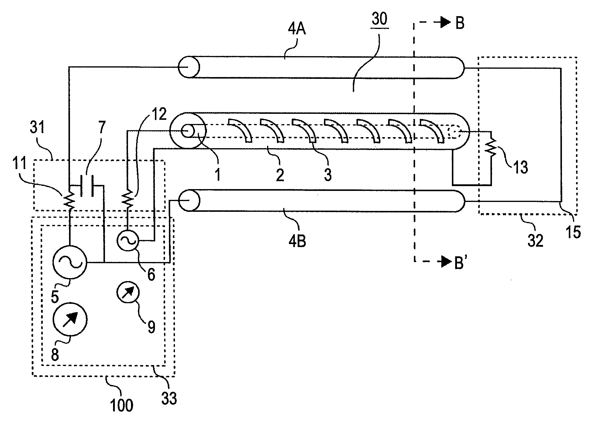
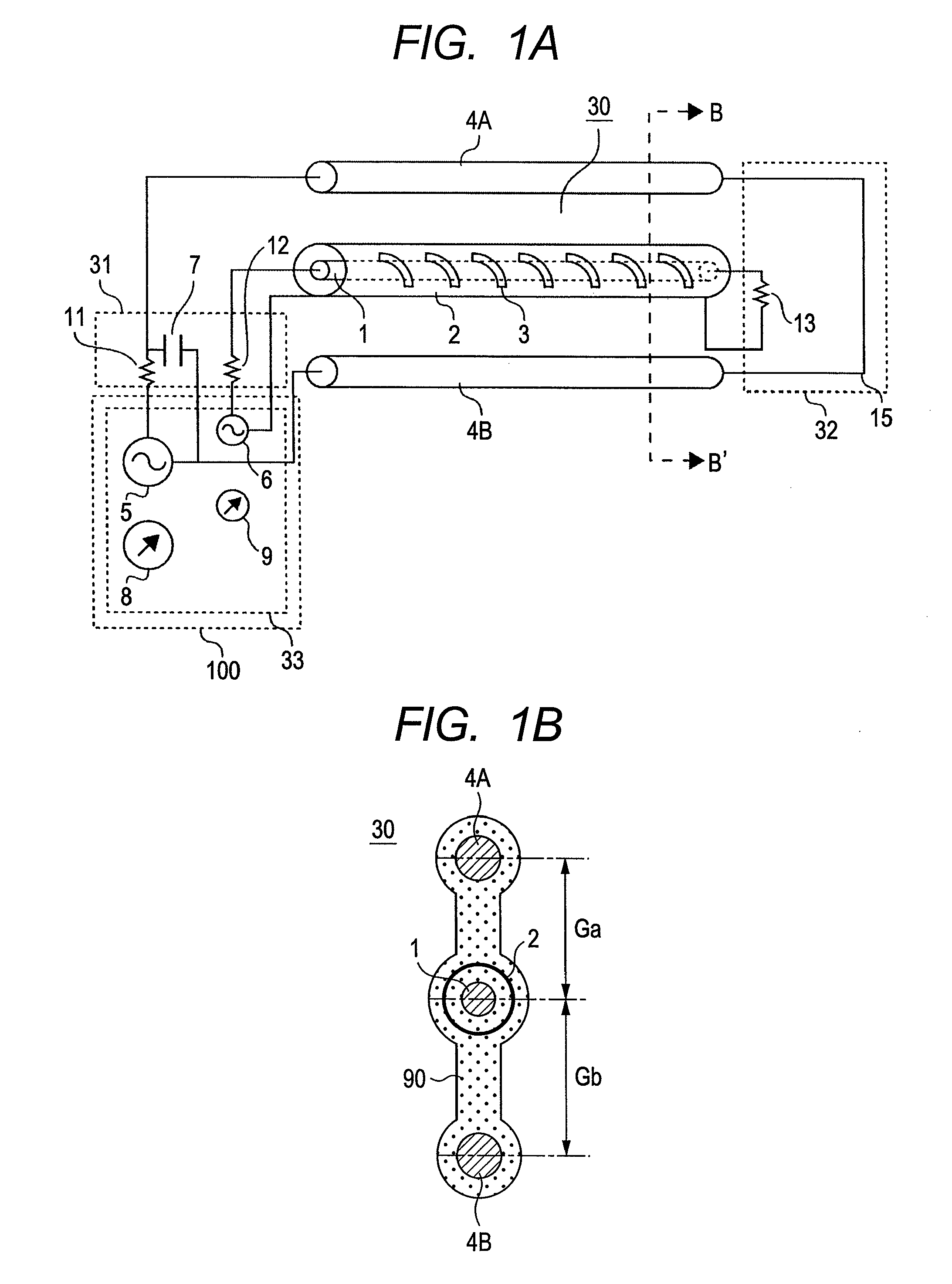
[0072]FIG. 1A is a configuration diagram of a base station apparatus including a low / high frequency shared leakage antenna according to the first embodiment of the present invention. FIG. 1B is a cross-sectional view taken along the line B-B′ of FIG. 1A.

[0073]The base station apparatus of the first embodiment includes a low / high frequency shared leakage antenna 30 and a base station 100. The base station 100 includes a transceiver 33. It should be noted that a configuration of the base station will be described in detail in the following embodiments. The low / high frequency shared leakage antenna 30 includes a high-frequency leakage coaxial cable having a leakage coaxial inner conductor 1 and a leakage coaxial outer conductor 2, a termination circuit 32 through which the inner conductor and the outer conductor are coupled to each other at one end of t...

second embodiment

[0091]Next, a second embodiment of the present invention will be described. FIG. 4A is a diagram for showing a configuration of a base station apparatus including a low / high frequency shared leakage antenna with an open-type low / high frequency leakage coaxial cable according to the second embodiment of the present invention. FIG. 4B is a cross-sectional view taken along the line B-B′ of FIG. 4A.

[0092]The high-frequency leakage coaxial cable includes a leakage coaxial inner conductor 1 and a leakage coaxial outer conductor 2 on which slots 3 are formed. A gap G between the leakage coaxial cable and a conductor line 4 provided in parallel with the travelling direction is constant, namely, the leakage coaxial cable and the conductor line 4 are formed in parallel with each other. In the embodiment, the conductor line 4B of FIG. 4A is shared with the leakage coaxial inner conductor 1 to form a closed-loop structure. Specifically, the low / high frequency shared leakage antenna is configure...

third embodiment

[0097]FIG. 5 is a diagram for showing a configuration of a base station apparatus including an open-type low / high frequency leakage coaxial cable according to a third embodiment of the present invention. In the embodiment, one conductor line 4 is used, and the outer conductor 2 of the leakage coaxial cable in the first embodiment is shared with the other of the conductor lines to form a closed-loop structure. Specifically, the low / high frequency shared leakage antenna is configured using integrated three conductor lines. Other configurations are the same as those of the second embodiment. According to the embodiment, the total surface area of the conductor that radiates low-frequency electromagnetic waves is increased as compared to the second embodiment. Thus, resistance to current radiating low-frequency electromagnetic waves is reduced, and the efficiency of radiation of the electric power generated by the first transmitter circuit to outer spaces is improved. On the other hand, ...


PUM


Abstract

The present invention provides a high / low frequency dual wireless location detection and information transmission system which is high in reliability and maintainability, and can be easily installed.A leakage coaxial inner conductor and a conductor line provided in parallel are short-circuited at an end, a single leakage coaxial operation and a loop operation of the inner conductor and the conductor line are performed at the same time, the ID of a tag is communicated using magnetic fields which locally exist near the conductor line by the loop, and wireless position detection and information communications which are less affected by the influence of ambient environments due to electromagnetic waves in a closed area are realized by open-type lines.

Description

CLAIM OF PRIORITY[0001]The present application claims priority from Japanese Patent Applications JP 2010-022118 filed on Feb. 3, 2010 and JP 2010-183564 filed on Aug. 19, 2010, those contents of which are hereby incorporated by reference into this application.FIELD OF THE INVENTION[0002]The present invention relates to a low / high frequency shared leakage antenna, a base station apparatus and a close-range detection system using the antenna which detect whether or not an object exists using electromagnetic waves, and particularly to a low / high frequency shared leakage antenna, a base station apparatus and a detection system using the antenna which improve detection accuracy in a limited area where an object to be detected exists and are suitable for reducing the probability of false detection outside the limited area.BACKGROUND OF THE INVENTION[0003]As a conventional technique related to RFID, there has been known a technique called semi-active RFID in which electromagnetic waves in ...

Claims


Application Information

Patent Timeline
Patent Type & Authority Patents(United States)
IPC IPC(8): H01Q21/00H04W4/00H01Q1/50G06K7/10G06K17/00G06K19/07G06K19/077H01Q13/22H01Q21/06H01Q21/28H04B1/59H04B5/00
CPCG01S13/767H01Q5/40H01Q7/00H04B5/0018H01Q1/2216H01Q5/0072H01Q13/203
Inventor TAKEI, KENTAMURA, KAZUOKITANO, NOBUAKIKASHIMURA, SEIICHIHORI, HIROYUKIISHIKAWA, YASUO
Owner HITACHI LTD
Why Eureka
Try Eureka