

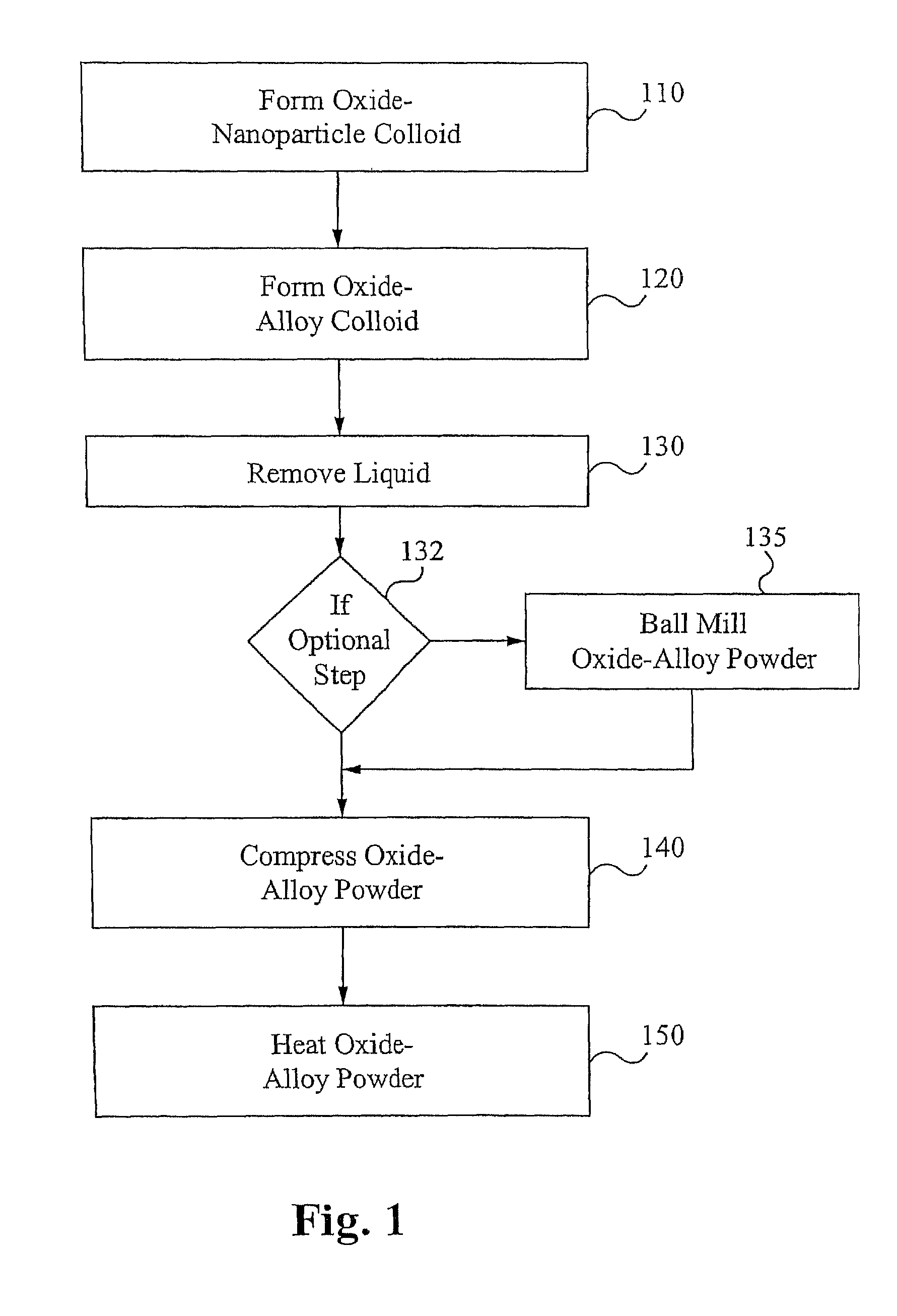
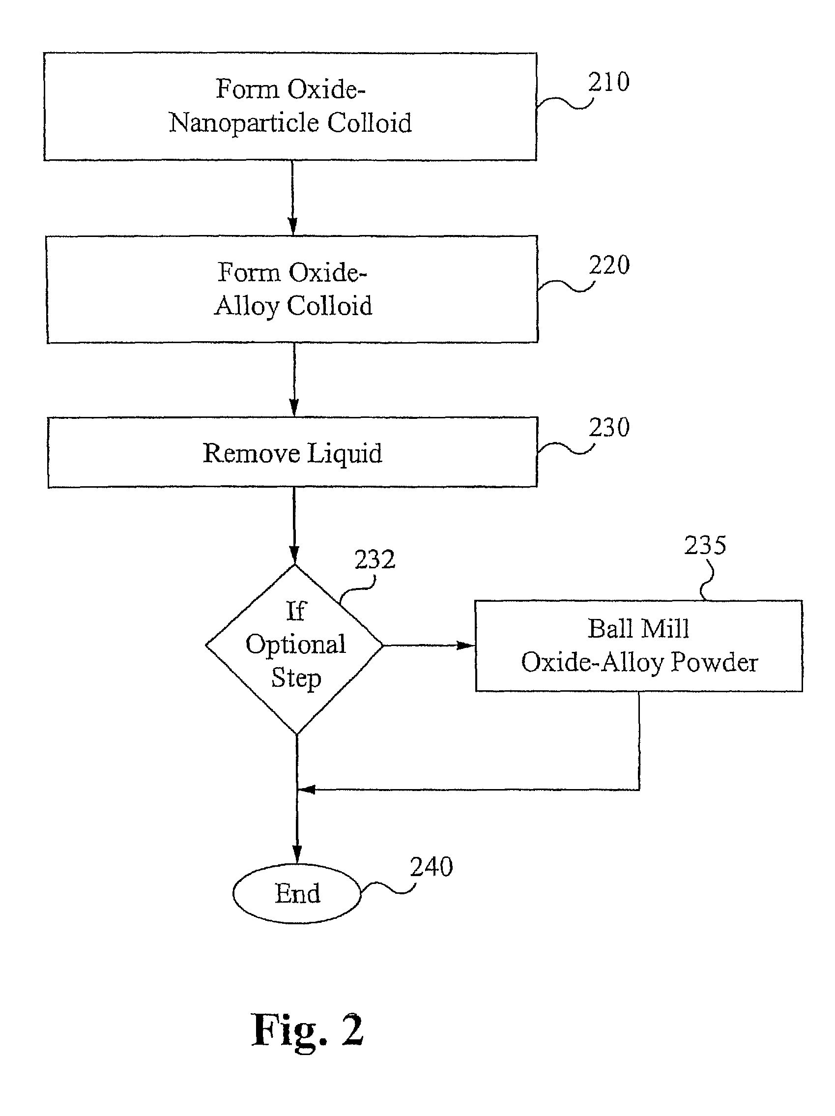
Method of forming oxide dispersion strengthened alloys
a technology of oxide dispersions and alloys, which is applied in the direction of catalyst activation/preparation, metal/metal-oxide/metal-hydroxide catalysts, and silicon compounds, etc., can solve the problem of metal embrittlement, reduce the ability of metals to resist bending and shear forces, and the current state-of-the-art has not developed a technology to form alloys. achieve the effect of enhancing the distribution of oxide-nanoparticl
- Summary
- Abstract
- Description
- Claims
- Application Information
AI Technical Summary
Benefits of technology
Problems solved by technology
Method used
Image

Examples
Embodiment Construction
[0019]The following description of the invention is provided as an enabling teaching of the invention which includes the best, currently known embodiment. One skilled in the relevant art will recognize that many changes can be made to the embodiment described, while still obtaining the beneficial results of the present invention. It will also be apparent that some of the desired benefits of the present invention can be obtained by selecting some of the features of the present invention without utilizing other features. Accordingly, those who work in the art will recognize that many modifications and adaptions to the present inventions are possible and can even be desirable in certain circumstances, and are a part of the present invention. Thus, the following description is provided as illustrative of the principles of the present invention and not in limitation thereof. The scope of the present invention is defined by the claims. The terms “nanoparticle,”“nanoparticle powder,” and “...
PUM
| Property | Measurement | Unit |
|---|---|---|
| diameter | aaaaa | aaaaa |
| diameter | aaaaa | aaaaa |
| diameter | aaaaa | aaaaa |
Abstract
Description
Claims
Application Information