Production of nanometric or sub-micrometric powders in continuous flux

a technology of nanometric powder and sub-micrometric powder, which is applied in the direction of laser beam welding apparatus, high temperature gas-gas reaction, chemical/physical/physicochemical processes, etc., can solve the problems of nanometric powder production process, nanometric powder availability and cost, and nanometric powder availability

Active Publication Date: 2014-09-02
COMMISSARIAT A LENERGIE ATOMIQUE ET AUX ENERGIES ALTERNATIVES
View PDF17 Cites 2 Cited by
  • Summary
  • Abstract
  • Description
  • Claims
  • Application Information

AI Technical Summary

Benefits of technology

[0016]The process of the invention ensures production of large quantities (greater than 500 grams / hour) of nanometric (5-100 nanometers) or sub-micrometric (100-500 nanometers) powders in continuous flux. The process of the invention favours hourly production rate and consumes almost all (over 90%) of the laser energy. It also produces powders having the same characteristics (chemical composition, structure, size, yields) as they leave the different interaction zones. Finally, it produces powders with chemical yields close to 100%.
[0017]The process of the invention changes the incident power density, as a function of the desired characteristics of the powder, by modifying the position of the injectors along the axis of the laser beam or by modulating the power as it leaves the laser.

Problems solved by technology

But the processes of manufacturing materials utilising nanometric powders are still not well managed due to the specific characteristics of these powders (reactivity, agglomeration .
. . ), their availability and their cost.
With respect to non-oxidised nanometric powders protection from oxidation, which can be necessary, can prove to be dangerous (pyrophoric effects).
This device does not ensure large-scale production of powders requiring the use of large power densities.
Also, the cross-section of the injectors cannot be elongated too significantly in the axis of the laser beam.
In fact, to the extent where the reagent flux is penetrated by the laser, there is progressive absorption of the energy until the remaining energy is no longer adequate.

Method used


Image

  • Production of nanometric or sub-micrometric powders in continuous flux
  • Production of nanometric or sub-micrometric powders in continuous flux
  • Production of nanometric or sub-micrometric powders in continuous flux

Examples


example 1

Production of Nanometric SiC Powders by Using a 5 kW Laser

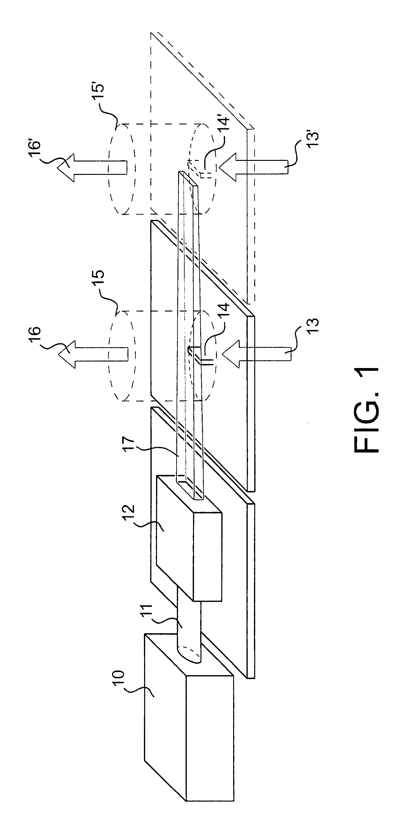
[0029]In this first example, as shown in FIG. 2 in a plan view, the system of the invention comprises a 5 kw CO2 laser 18 emitting at 10.6 μm and having a 17 mm cross-section, a periscope 19, a flat mirror 20, spherical lenses 21, 22 and 27, spherical mirrors 23 and 24 and two kaleidoscopes 25 and 26. Two possible embodiments, corresponding to two routes 30 and 31 of the laser beam are possible. The first route 30 creates a beam cross-section of 50 mm in width and 10 mm in height. The beam is first reflected by the flat mirror 20 then passes through the spherical lens 22, the kaleidoscope 26 and the spherical lens 27. The second route 31 corresponds to a beam cross-section of width 50 mm and height 300 μm. The beam is first reflected by the flat mirror 20, the position of which is changed relative to the previous mode, then it passes through the spherical lens 21, the kaleidoscope 25, and is reflected by the spherical mirrors...

example 2

Production of Nanometric SiC Powders from a Mixture of Silane (SiH4) and Acethylene (C2H2) by Using a 1 kW Laser

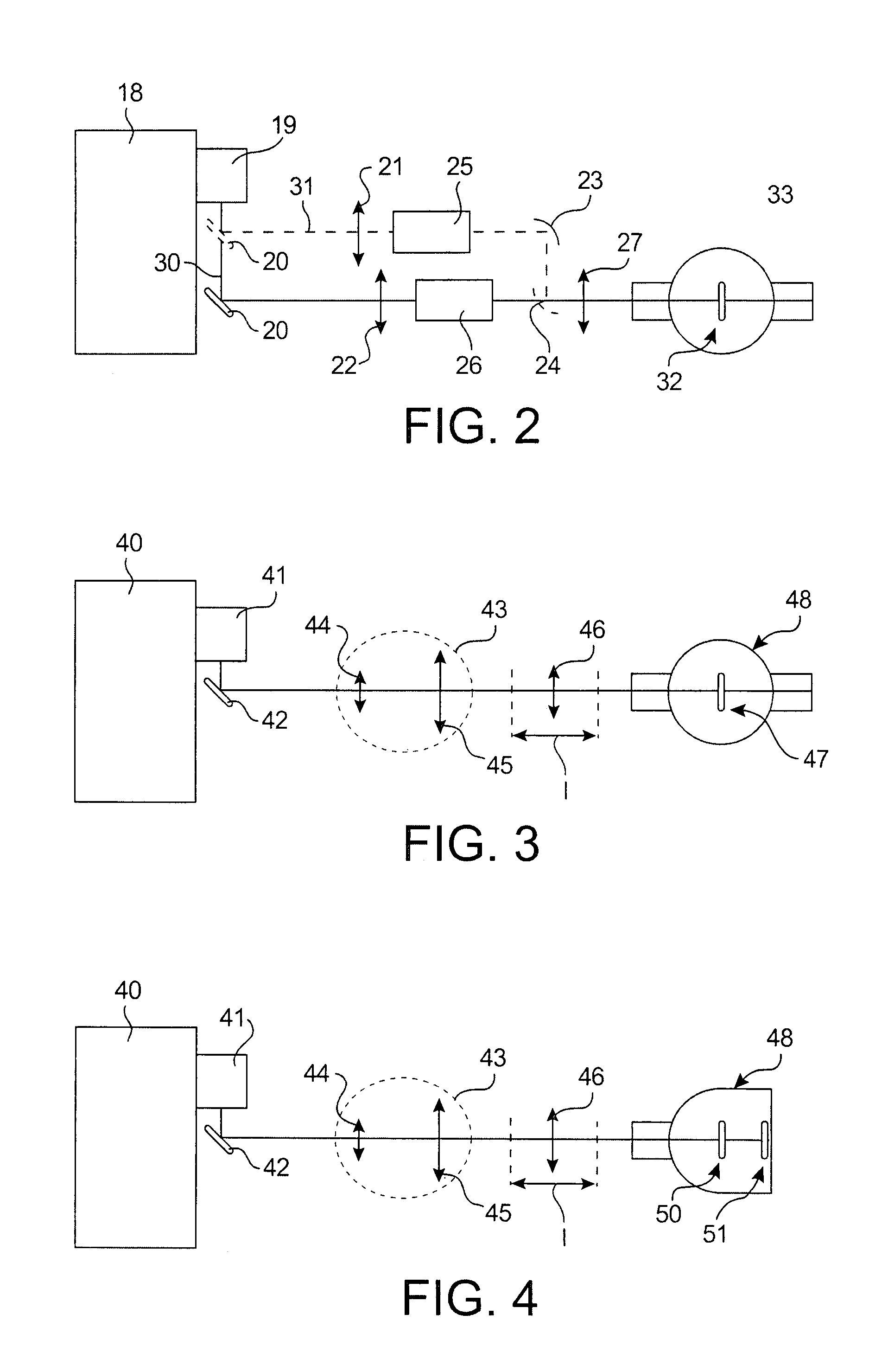
[0034]As shown in FIG. 3, the system of the invention comprises an laser 40, a periscope 41, a flat mirror 42, an afocal 43 and a cylindrical lens 46. The afocal 43 helps to enlarge the size of the beam to the desired dimension in width at the level of the interaction zone with the flux of reagents. It can be composed of two convergent cylindrical lenses 44 and 45, its magnification being supplied by the ratio of the focal distances of these lenses.

[0035]Once the cross-section of the beam is magnified, the cylindrical lens 46 focuses the beam at the level of the interaction zone 47 with the flux of reagents in the reactor 48. The width in cross-section of the beam is defined by the afocal. By varying the position of the lens over a length l, the height in cross-section of the beam can be varied at the level of the synthesis zone (when viewed more or less far from the focal...

example 3

Production of Nanometric SiC Powders from a Mixture of Silane (SiH4) and Acethylene (C2H2) by Using a 5 kW Laser

[0037]This example corresponds to the previous example applied to a multi-zone system 50 and 51 illustrated in FIG. 4. Several reagent injectors consume maximum power for synthesis. In this case, the losses by absorption are compensated by the concentration of the beam and it is simply a matter of positioning the injectors such that the incident power density is identical to the entry of the reagent beam from one injector to the other. In the previous example, as it leaves the lens 46, the beam converges. By placing a first injector in front of the focal point, other injectors can be placed one after another. The parameter defining the positioning of the injectors relative to one another is thus the power density. This is the ratio of the incident power on the surface of the cross-section of the beam. The preferred value for this parameter depends on the nature of powders ...


PUM

PropertyMeasurementUnit
sizesaaaaaaaaaa
sizesaaaaaaaaaa
sizesaaaaaaaaaa

Abstract

A system and process for production of nanometric or sub-micrometric powders in continuous flux under the action of laser pyrolysis in at least one interaction zone between a beam emitted by a laser and a flux of reagents emitted by an injector, in which the laser is followed by optical means for distributing the energy of the beam emitted by the latter according to an axis perpendicular to the axis of each flux of reagents, in an elongated cross-section having adjustable dimensions at the level of this at least one interaction zone.

Description

CROSS REFERENCE TO RELATED APPLICATIONS OR PRIORITY CLAIM[0001]This application is a national phase of International Application No. PCT / FR2005 / 050929 entitled “System And Method For Continuous Flow Production Of Nanometric Or Sub-Micrometric Powders By The Action Of A Pyrolytic Laser”, which was filed on Nov. 7, 2005, which was not published in English, and which claims priority of the French Patent Application Nos. 04 52578 filed Nov. 9, 2004.TECHNICAL FIELD[0002]The present invention relates to a system and a process for production of nanometric or sub-micrometric powders in continuous flux under the action of a laser pyrolysis.PRIOR ART[0003]In the field of dense materials manufactured by metallurgy of powders, properties of resistance to breakage, hardness, resistance to wear, for mechanical and thermomechanical applications, tend to improve to the extent that the size of the powder grains decreases. When this size reaches the nanometric domain (1 to 100 nanometers) these prope...

Claims


Application Information

Patent Timeline
Patent Type & Authority Patents(United States)
IPC IPC(8): B23K26/00
CPCB01J12/02B01J12/005B01J19/121Y02E60/122
Inventor TENEGAL, FRANCOISGUIZARD, BENOITHERLIN-BOIME, NATHALIEPORTERAT, DOMINIQUE
Owner COMMISSARIAT A LENERGIE ATOMIQUE ET AUX ENERGIES ALTERNATIVES
Why Eureka
Try Eureka