
Synthesis of Silicon Nanocrystals by Laser Pyrolysis

a technology of laser pyrolysis and silicon nanoparticles, which is applied in the field of synthesis of siliconcontaining nanoparticles, can solve the problems of inability to meet the requirements of industrial applications, low yield, and long implementation time of liquid phase approaches, etc., and achieves the effects of increasing the production rate, increasing the size of particles, and limited particle growth time in the reaction zon

Inactive Publication Date: 2013-07-25
COMMISSARIAT A LENERGIE ATOMIQUE ET AUX ENERGIES ALTERNATIVES
View PDF14 Cites 0 Cited by
  • Summary
  • Abstract
  • Description
  • Claims
  • Application Information

AI Technical Summary

Benefits of technology

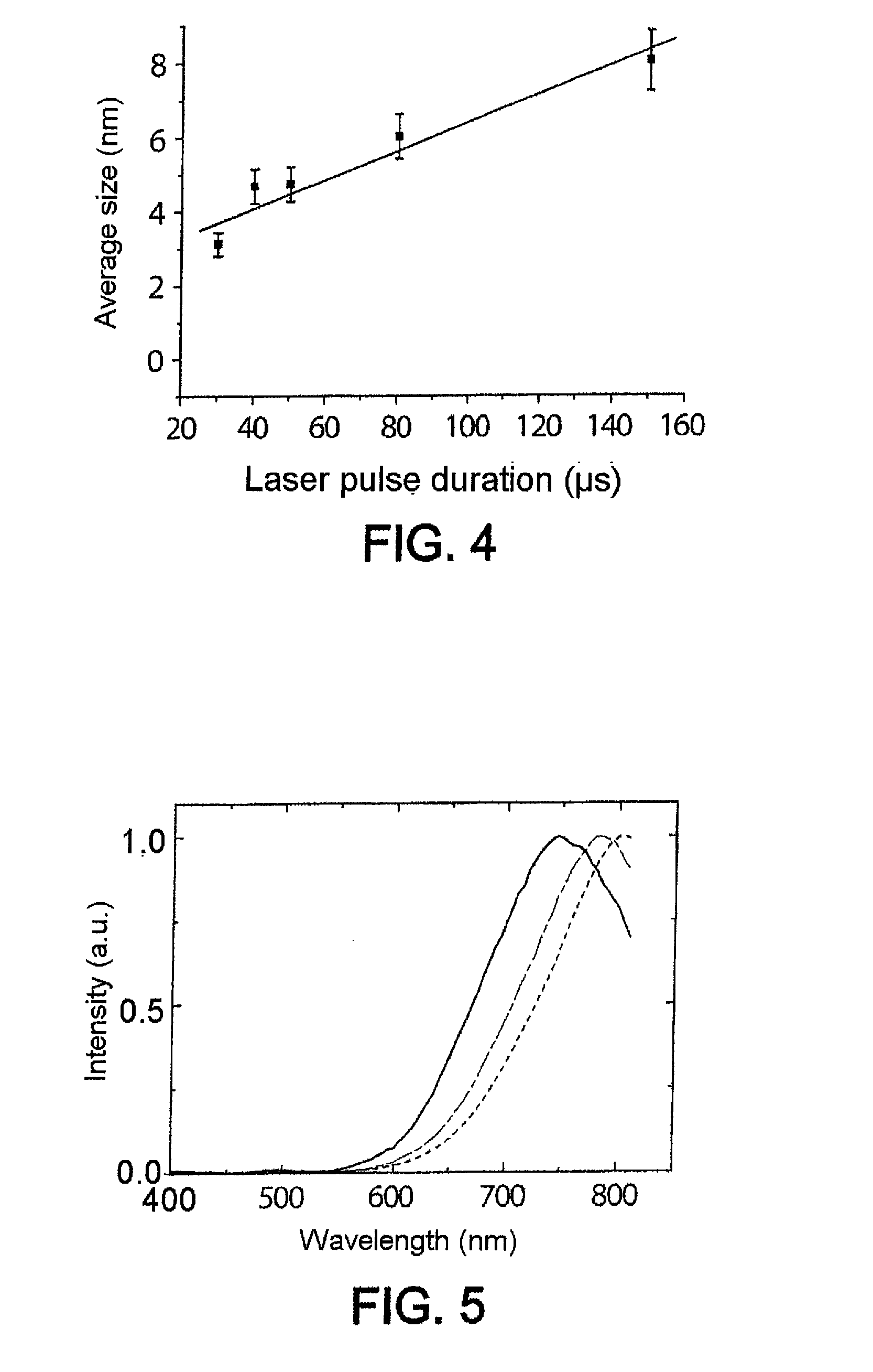
This approach achieves record production rates exceeding 700 milligrams per hour of nanoparticles with sizes below 10 nm, ensuring photoluminescence without the need for additional treatment steps, thereby addressing the inefficiencies of existing techniques.

Problems solved by technology

However, the development of devices based on such nanoparticles has been retarded by the lack of availability of said nanoparticles.
Furthermore, approaches in liquid phase, such as what is called “reverse micelle” synthesis, or else supercritical solutions, are often lengthy to implement and give low yields.
However, the very small quantities obtained (only a few milligrams) seem incompatible with industrial applications.
However, no details are given about the effect of these parameters on the particle sizes.
Furthermore, increasing the overlap area would itself also lead to an increase in the interaction time and therefore in the size of the crystals obtained.
Thus, as regards laser pyrolysis, there is presently no solution making it possible to obtain, in weighable amount and in a single step, silicon nanoparticles having a size of 10 nm or less and exhibiting photoluminescence properties, for example after simple passivation in air.

Method used


Image

  • Synthesis of Silicon Nanocrystals by Laser Pyrolysis
  • Synthesis of Silicon Nanocrystals by Laser Pyrolysis
  • Synthesis of Silicon Nanocrystals by Laser Pyrolysis

Examples


Embodiment Construction

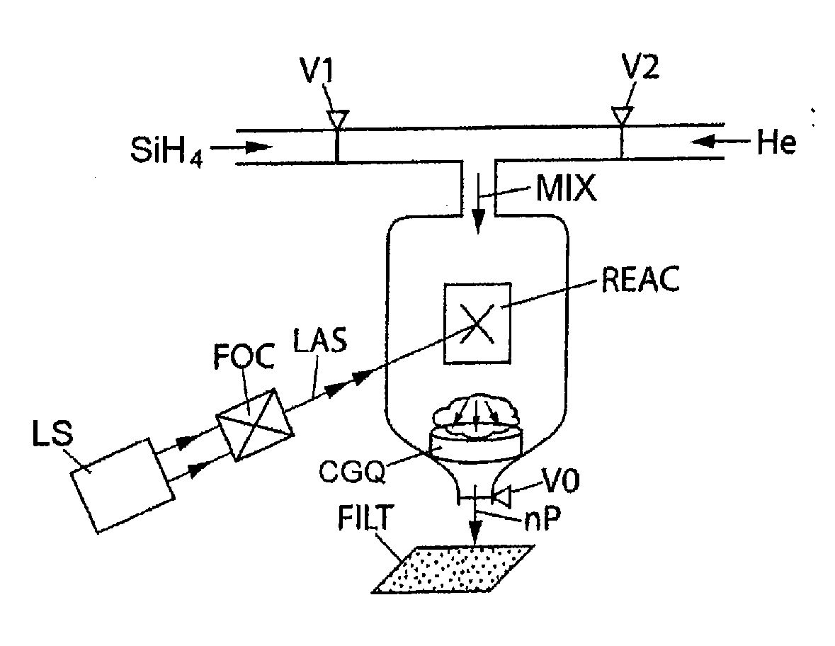
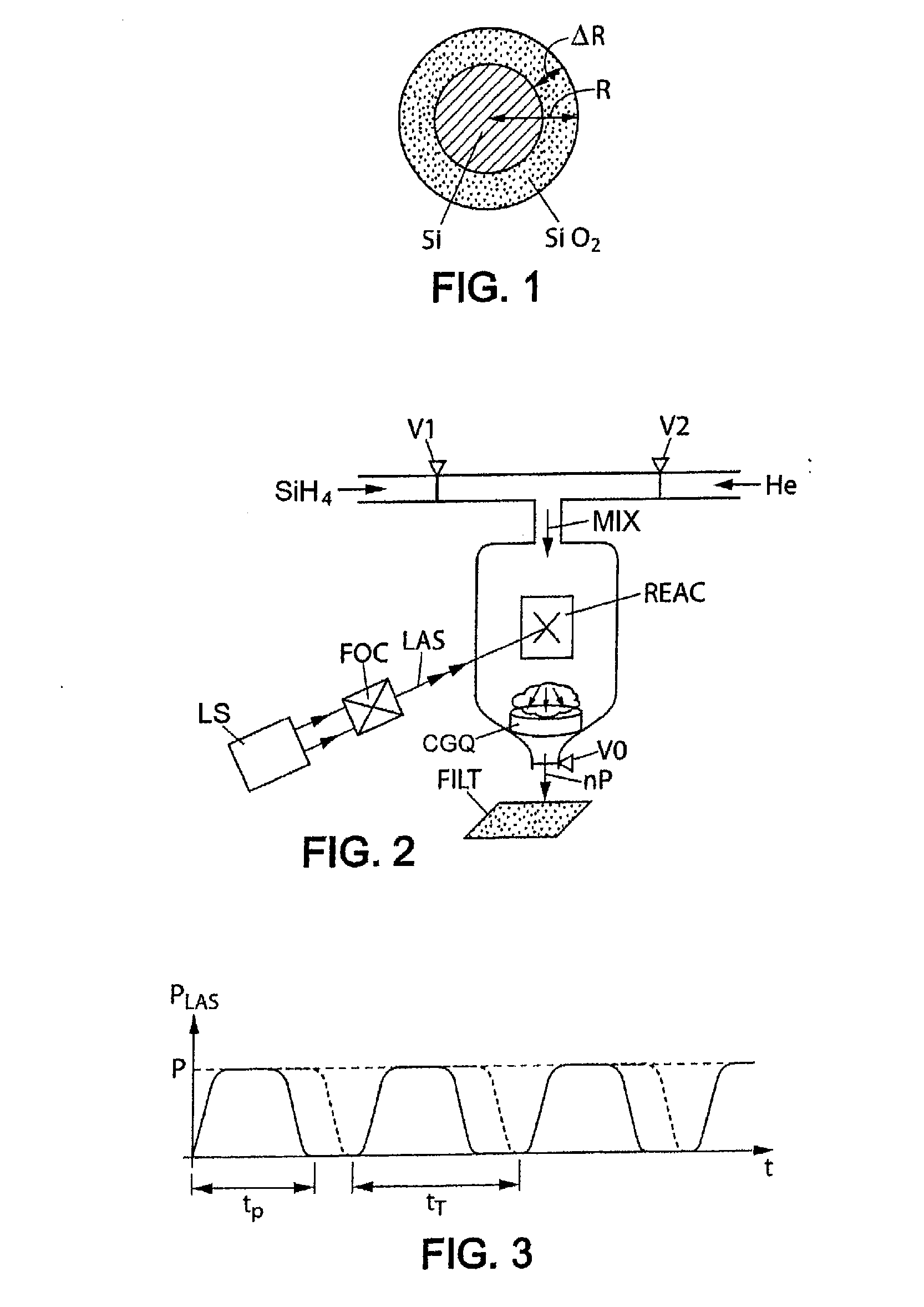
[0041]Referring to FIG. 2, a precursor containing the element silicon, in gaseous form, and more precisely silane SiH4 in the exemplary embodiment described, is mixed with an inert gas, here helium He, as carry fluid. Preferably, the dilution of the precursor in the carrier fluid is between 1 / 10 and 1 / 30. In the embodiment described, the dilution is controlled by the two valves V1 and V2 in FIG. 2. The mixture of the two gases, with the reference MIX in FIG. 2, is conveyed into a reaction chamber REAC at a pressure controlled by a pressure gauge V0. The pressure of the mixture is preferably between 150 and 300 torr. A mass flow rate regulator system, comprising the valves V1 and in particular V2, is used for also controlling the gas flow rate and in particular the carrier stream (arrow He) in the reaction chamber REAC. The carrier fluid flow rate here is between 600 and 2000 sccm, which corresponds, under the experimental conditions of the trials carried out and described below, to ...


PUM

PropertyMeasurementUnit
sizeaaaaaaaaaa
sizeaaaaaaaaaa
peak wavelengthaaaaaaaaaa

Abstract

The invention relates to the synthesis of silicon-containing nanoparticles by laser pyrolysis. For this purpose: a precursor (SIH4) containing the element silicon is conveyed, by a transport fluid (He), into a pyrolysis reactor (REAC); laser radiation (LAS) is applied, in the reactor, to a mixture that the transport fluid and the precursor form; and silicon-containing nanoparticles (nP) are recovered at the exit of the reactor. In particular, the power of the laser radiation is controlled. Furthermore, the effective pulse duration is controlled within a laser firing period. Typically, for a power greater than 500 watts and a pulse duration greater than 40% of a laser firing period, nanoparticles having a crystalline structure with a size of less than or of the order of one nanometer are obtained at a rate greater than or of the order of 80 milligrams per hour. Under optimum conditions, a record rate of greater than 740 milligrams per hour was able to be obtained.

Description

TECHNICAL FIELD[0001]The present invention relates to the synthesis of silicon-containing nanoparticles of crystalline form.BACKGROUND OF THE DISCLOSURE[0002]Referring to FIG. 1, a crystalline silicon nanoparticle Si naturally includes, on the surface, a layer of oxide SiO2, the thickness OR of which is about one tenth of the overall diameter D of the nanoparticle. By quantum confinement, such nanoparticles, having a crystalline silicon core of the order of 10 nanometers or less in size, exhibit photoluminescence properties. The emission wavelength of the photons through the photoluminescence effect is shorter the smaller the size of the crystalline core of the nanoparticles (from 10 nm for emission in the red / infrared to 3 nm for emission in the red / yellow). Moreover, it is also possible to modify the emission wavelengths, especially by modifying the composition of the nanoparticles. For example, it is pointed out that carbon-containing (Si—C) nanoparticles and / or germanium-contain...

Claims


Application Information

Patent Timeline
Patent Type & Authority Applications(United States)
IPC IPC(8): B01J19/12
CPCB01J19/121B01J2219/00123C01B33/029B82Y30/00C01B33/021B01J2219/00162
Inventor HERLIN-BOIME, NATHALIESUBLEMONTIER, OLIVIERLACOUR, FREDERIC
Owner COMMISSARIAT A LENERGIE ATOMIQUE ET AUX ENERGIES ALTERNATIVES
Learn More