
Multi-mode optoelectronic oscillator

a multi-mode optoelectronic and oscillator technology, applied in the field of multi-mode optoelectronic oscillators, can solve the problems of increasing the noise of the system, and inconvenient operation of the system, so as to reduce the noise floor, reduce the noise, and the current system is more selective

Inactive Publication Date: 2014-09-02
UNITED STATES OF AMERICA
View PDF3 Cites 2 Cited by
  • Summary
  • Abstract
  • Description
  • Claims
  • Application Information

AI Technical Summary

Benefits of technology

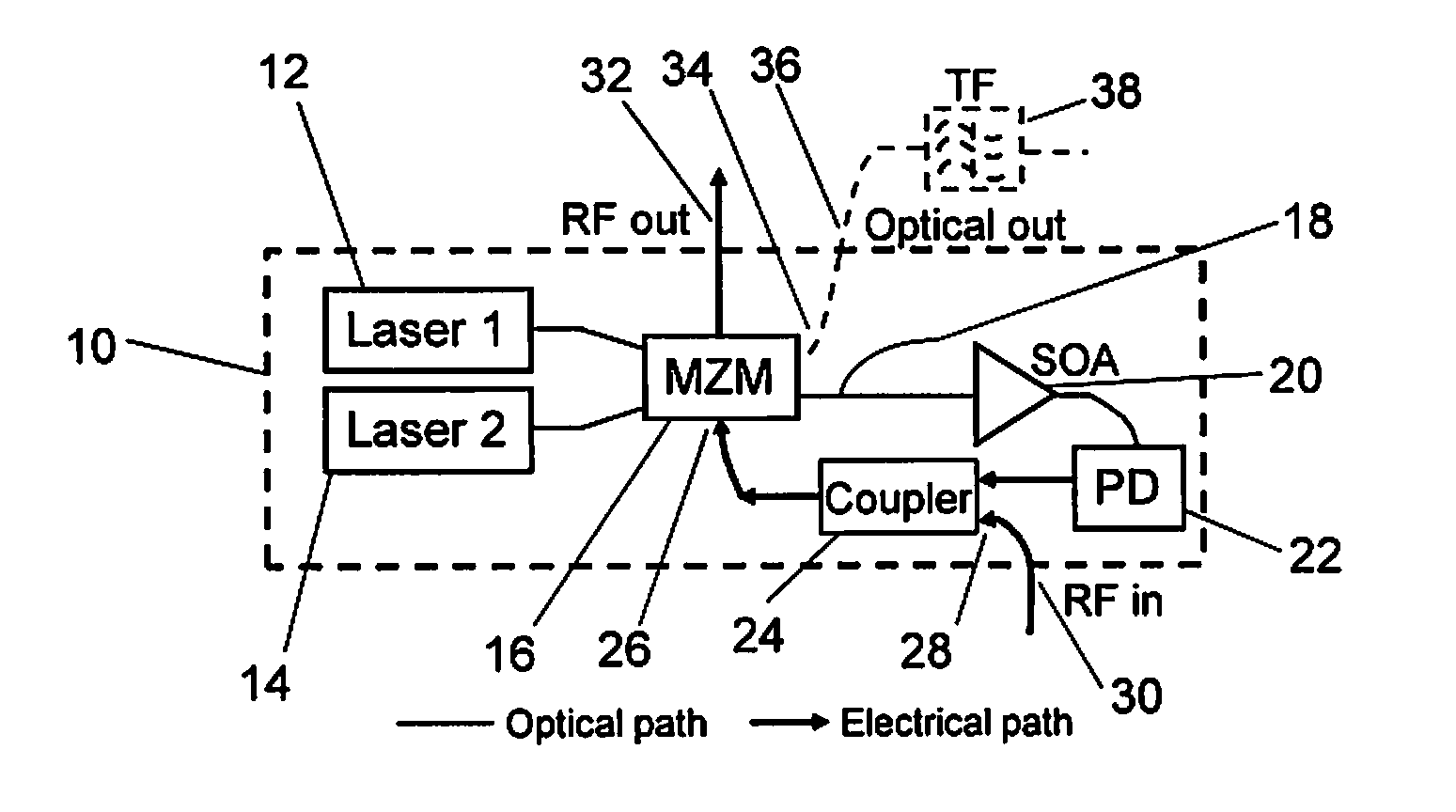
[0009]Using one laser causes the MM-OEO to operate with one set of cavity modes, while adding the second laser switches the MM-OEO to operate at the complementary set of cavity modes. The system selectively provides gain to RF frequencies that match the cavity modes of the MM-OEO with either one or two lasers operating. The ability to switch between modes in a single system allows the OEO to detect twice as many frequencies than the prior art.

Problems solved by technology

However, these methods have not focused on selectively amplifying very low power RF signals.
This method used a single laser and an electronic RF amplifier which increases the noise of the system.
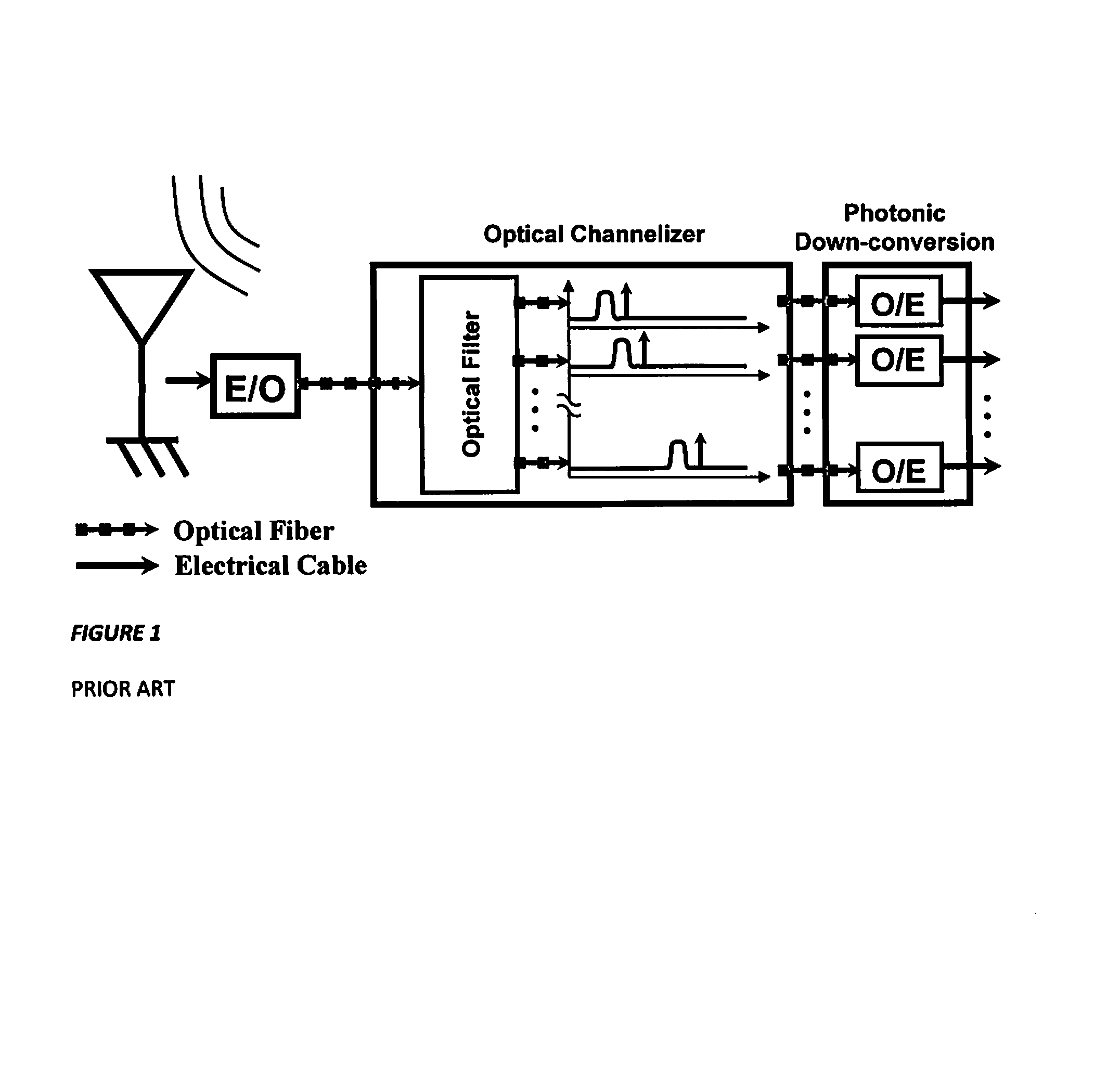
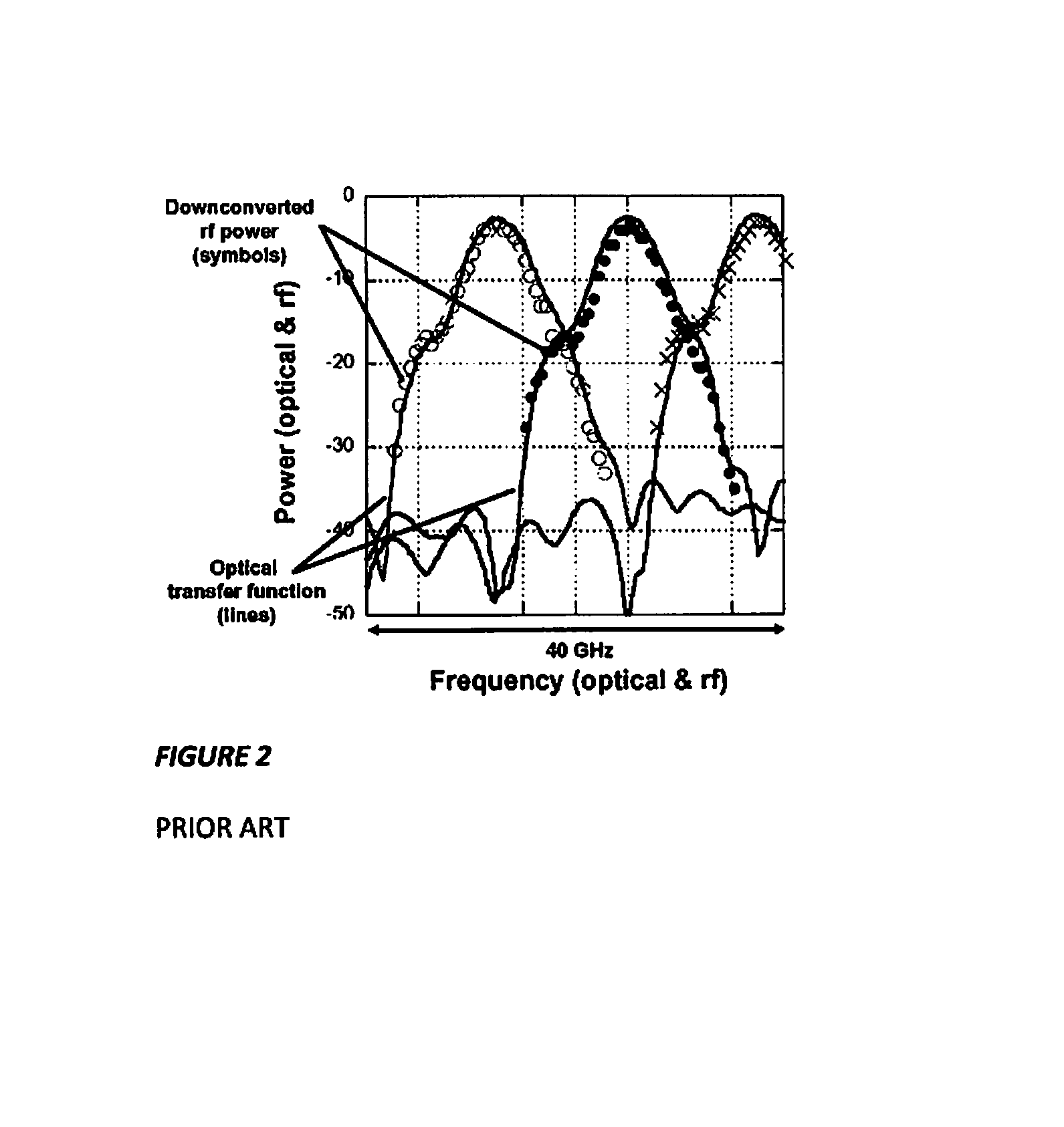
The use of a long fiber erbium-doped fiber amplifier left this system with closely spaced cavity modes not useful for RF channelization.
Optical filter technology is bulky and not narrow enough.
Other methods have been demonstrated but provide no selective gain.
While one can use a filter and amplifier, it is expensive and bulky.

Method used


Image

  • Multi-mode optoelectronic oscillator
  • Multi-mode optoelectronic oscillator
  • Multi-mode optoelectronic oscillator

Examples


Embodiment Construction

[0021]As shown in FIGS. 5A-B, the multi-mode optoelectronic oscillator (MM-OEO) 10 of the invention, below threshold, accepts an injected RF signal that forces the cavity 30 above threshold when it matches one of the cavity modes while adding loss to any signal outside the cavity modes. Optoelectronic oscillators provide exceptional bandwidth and frequency coverage. Employing the array with the modes shifted between each OEO covers a broad RF spectrum.

[0022]Referring now to FIG. 6A, an embodiment of an OEO 10 of the invention consists of two lasers 12 and 14 (e.g. a JDS CQF938 and / or an EM4 EM253-080) that are input to a dual-input, dual-output Mach-Zehnder modulator (MZM) 16. One example of this type of MZM is the EOSPACE AZ-2×2-NRL but other 2×2 MZMs can be used. One of the outputs 18 of the MZM is connected to an SOA (semiconductor optical amplifier) 20 and the amplified signal is sent to a photodetector 22. An exemplary SOA is a Covega BOA-6324 and an exemplary photodetector is ...


PUM

PropertyMeasurementUnit
frequencyaaaaaaaaaa
wavelengthaaaaaaaaaa

Abstract

A multi-mode optoelectronic oscillator (MM-OEO) includes an OEO cavity having an input for receiving an RF signal and an RF output. The OEO cavity includes a) a first laser having a first laser output, a second laser having a second laser output, b) a modulator having i) a first input coupled to the first laser output, ii) a second input coupled to the second laser output, iii) a third input, iv) a first modulator output, and v) a second modulator output, c) a semiconductor optical amplifier (SOA) having an input coupled to the first modulator output and having an SOA amplified output, d) a photodetector coupled to the SOA amplified output and having an output, and e) a coupler having an input coupled to the photodetector output and having a first output coupled to the third modulator input and a second output, whereby an amplified RF signal is produced at the OEO RF output.

Description

CROSS-REFERENCE TO RELATED APPLICATIONS[0001]This Application claims the benefit of U.S. Provisional Application 61 / 617,251 filed on Mar. 29, 2012 and incorporated herein by reference.FIELD OF THE INVENTION[0002]The invention is directed to a method of using a two laser, multi-mode optoelectronic oscillator (OEO) for detecting unknown low power RF signals, and more particularly the invention is directed to the OEO.BACKGROUND OF THE INVENTION[0003]The ability to detect very low power unknown RF signals is important in applications ranging from civilian to military, e.g. as described in G. W. Anderson, D. C. Webb, A. E. Spezio, and J. N. Lee, “Advanced channelization for RF, microwave and millimeterwave applications,”Proc. IEEE, vol. 79, pp. 355-388, 1991, and in J. Raza, A.-J. Boonstra, and A.-J. van der Veen, “Spatial filtering of RF interference in radio astronomy,”IEEE Sig. Proc. Lett., vol. 9, pp. 64-67, 2002. Multiple methods using photonics have been proposed to detect unknown ...

Claims


Application Information

Patent Timeline
Patent Type & Authority Patents(United States)
IPC IPC(8): H04B10/00G02F1/01H03B17/00H03C7/00
CPCG02F1/0102H03B17/00H03C7/00H04B2210/006
Inventor DEVGAN, PREETPAUL SURICK, VINCENT JWILLIAMS, KEITH J
Owner UNITED STATES OF AMERICA
Learn More