Construction machine and industrial vehicle having power supply system

a technology of power supply system and construction machine, which is applied in the direction of electric/hybrid propulsion, dc motor stopper, process and machine control, etc., can solve the problems of inability to recover and most regenerative energy in regenerative braking lost, so as to reduce the battery capacity, recover regenerative energy, and high efficiency

Active Publication Date: 2014-09-09
NIHON KENKI CO LTD
View PDF7 Cites 25 Cited by
  • Summary
  • Abstract
  • Description
  • Claims
  • Application Information

AI Technical Summary

Benefits of technology

[0014]The present invention has the abovementioned constitution, so it can recover regenerative energy with high efficiency and decrease the battery capacity.

Problems solved by technology

Even when a vehicle has a large capacity battery, if the battery is a lead battery, it may happen that most regenerative energy in regenerative braking is lost and cannot be recovered since the lead battery is not suitable for rapid charging.

Method used


Image

  • Construction machine and industrial vehicle having power supply system
  • Construction machine and industrial vehicle having power supply system
  • Construction machine and industrial vehicle having power supply system

Examples


first embodiment

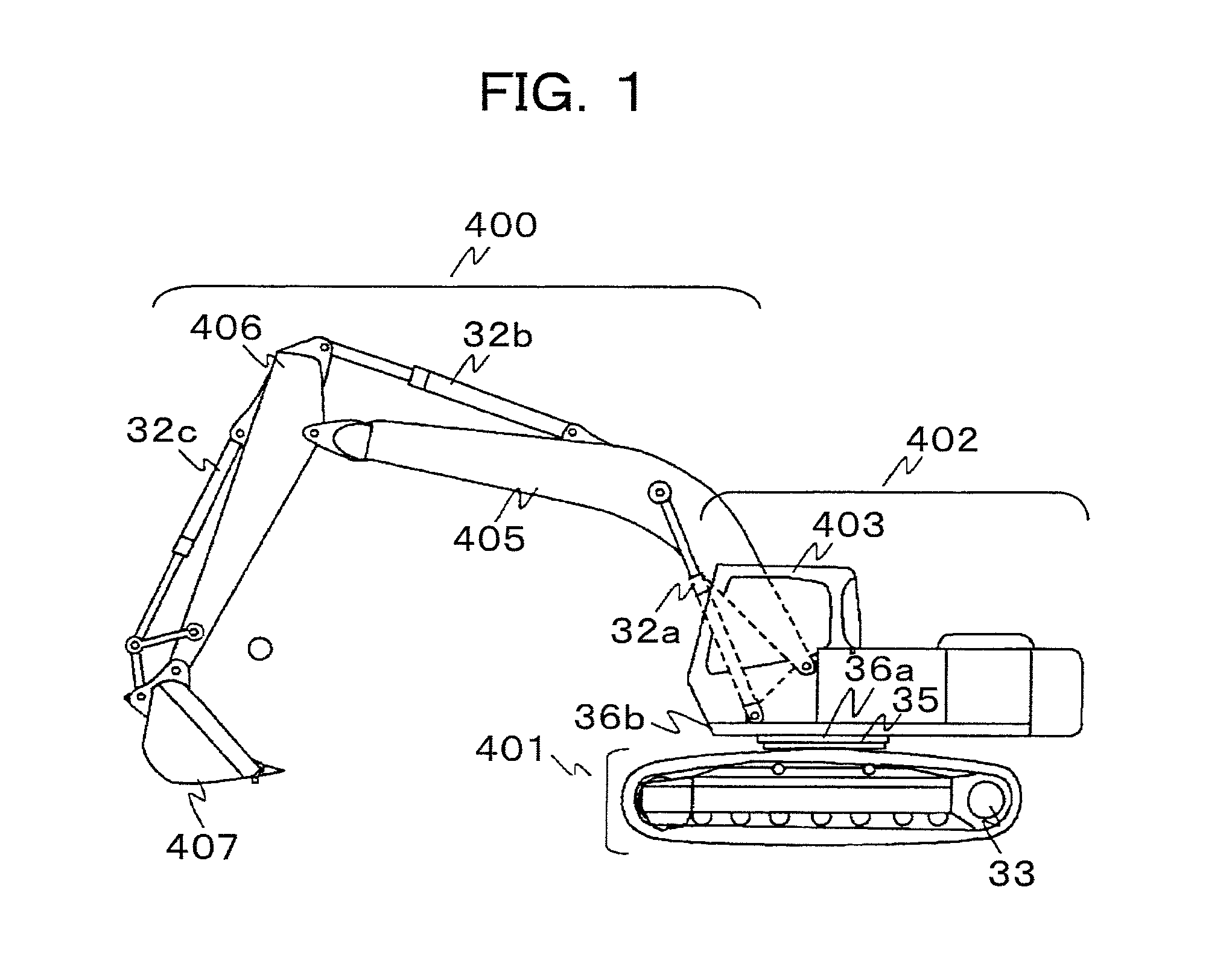
[0024]FIG. 1 illustrates a hybrid hydraulic shovel provided with a power supply system according to the first embodiment.

[0025]In FIG. 1, the hydraulic shovel includes a traveling body 401 and a swing body 402 and the traveling body 401 is driven by a traveling hydraulic motor 33. A driver seat 403 is provided on the front left side in the swing body 402 and a multi-jointed working device 400 having a boom 405, an arm 406 and a bucket 407 is provided on the front right side.

[0026]The boom 405, arm 406, and bucket 407 are driven respectively by a boom cylinder 32a, arm cylinder 32b, and bucket cylinder 32c which are hydraulic actuators.

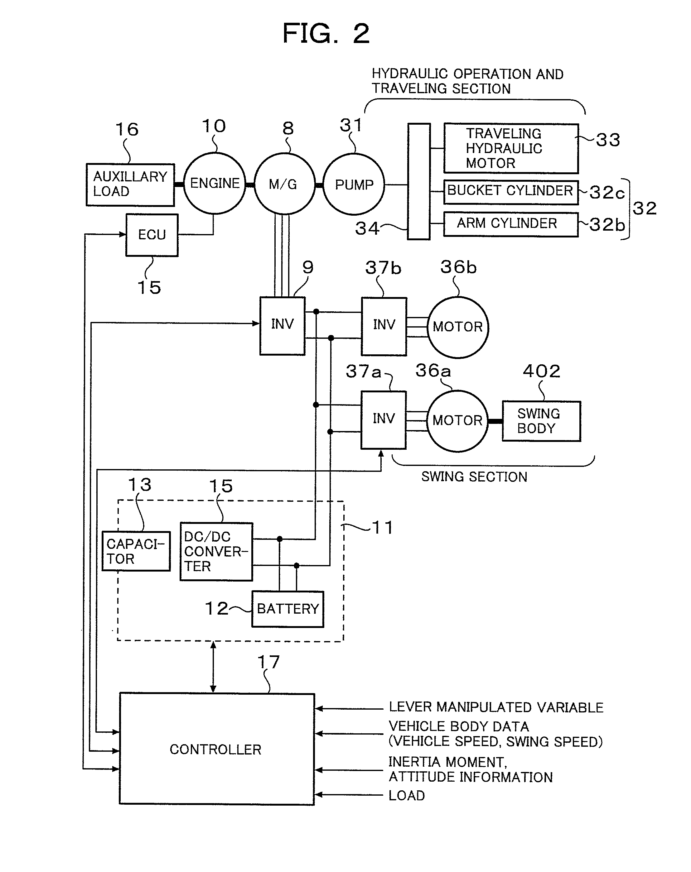
[0027]FIG. 2 shows the configuration of the driving section of the hybrid hydraulic shovel shown in FIG. 1 and the configuration of the power supply system 1 incorporated therein according to the first embodiment.

[0028]The traveling hydraulic motor 33 and hydraulic actuators for driving the working device (arm cylinder 32b, bucket cylinder 32c) are dri...

second embodiment

[0081]Next, the second embodiment will be described.

[0082]FIG. 6 illustrates a forklift provided with a power supply system according to the second embodiment.

[0083]FIG. 7 is a view illustrating details of the power supply system 1 shown in FIG. 1 and the control system of the forklift. In FIG. 7, the power supply system 1 includes a battery 12 and a capacitor 13. The battery 12 is a lead battery or lithium-ion battery and in this case it is assumed to be a lead battery with a voltage of 48 V. The capacitor 13 may be an electric double layer capacitor having a capacity of several tens of farads.

[0084]Normally a current of approximately 150 A flows in an inverter 4 and if the load is large, a current of 300 A to 400 A may flow in it. If a lead battery is used as the battery 12, a capacity of 400 Ah or so is required depending on the forklift workload and the number of working hours per day.

[0085]The forklift 2 includes a mast 7, a fork 8, pedals 9 for an accelerator and a brake, an A...


PUM


Abstract

A construction machine or industrial vehicle having a power supply system which includes a chargeable and dischargeable capacitor and a feeder circuit connecting a battery and the capacitor to a load capable of power running and regeneration. The capacitor is connected through a DC / DC converter which includes a controller that controls energy charged or discharged by the capacitor through the DC / DC converter to the load. The controller includes a power running / regeneration operation estimater which estimates an operation pattern including a point of change between power running and regeneration modes of the motor, or DC current supplied to an inverter, or control lever information and previously stored operation pattern information, and a capacitor target voltage calculator which controls an output command value of the DC / DC converter according to the estimated operation pattern so that a capacitor target voltage sequentially decreases in power running and sequentially increases in regeneration.

Description

TECHNICAL FIELD[0001]The present invention relates to construction machines and industrial vehicles which are provided with a power supply system and more specifically to construction machines and industrial vehicles which are provided with a power supply system suitable for hydraulic shovels, forklifts and the like.BACKGROUND ART[0002]A hybrid vehicle using a motor for a vehicle driving system, electric vehicle or battery forklift is provided with a battery for driving the traveling motor, in which AC power is supplied from the battery to the motor through an inverter.[0003]Industrial vehicles such as battery forklifts employ lead batteries as power sources and taking into consideration the energy which these industrial vehicles consume during traveling or work operation, the battery capacity must be large enough.[0004]Even when a vehicle has a large capacity battery, if the battery is a lead battery, it may happen that most regenerative energy in regenerative braking is lost and c...

Claims


Application Information

Patent Timeline
Patent Type & Authority Patents(United States)
IPC IPC(8): B60L1/00
CPCB60L1/00B60L1/20B60L7/16B60L11/005B60L2200/40B60L2200/42H02J7/345Y02T10/7022E02F9/2091H02P3/14E02F9/2075B66F9/24Y02P90/60B60L1/003B60L2210/10B60L2240/547B60L2240/549B60L50/40Y02T10/64Y02T10/70Y02T10/72
Inventor IZUMI, SHIHOKANEKO, SATORUIKIMI, TAKASHIMASANO, NOBUO
Owner NIHON KENKI CO LTD
Why Eureka
Try Eureka