Adjustable hole cutters

a hole cutter and adjustment technology, applied in the field of adjustment hole cutters, can solve the problems of insufficient power of drill for cutting operation, inability to easily cut materials such as ceramic tiles and sheet metal, and inability to easily adjust the cutting speed of drills, so as to reduce the power required to rotate the hole cutter, reduce the overall design of the hole cutting apparatus, and determine the position quickly

Active Publication Date: 2014-09-23
STENMAN BRUCE WINTER
View PDF31 Cites 38 Cited by
  • Summary
  • Abstract
  • Description
  • Claims
  • Application Information

AI Technical Summary

Benefits of technology

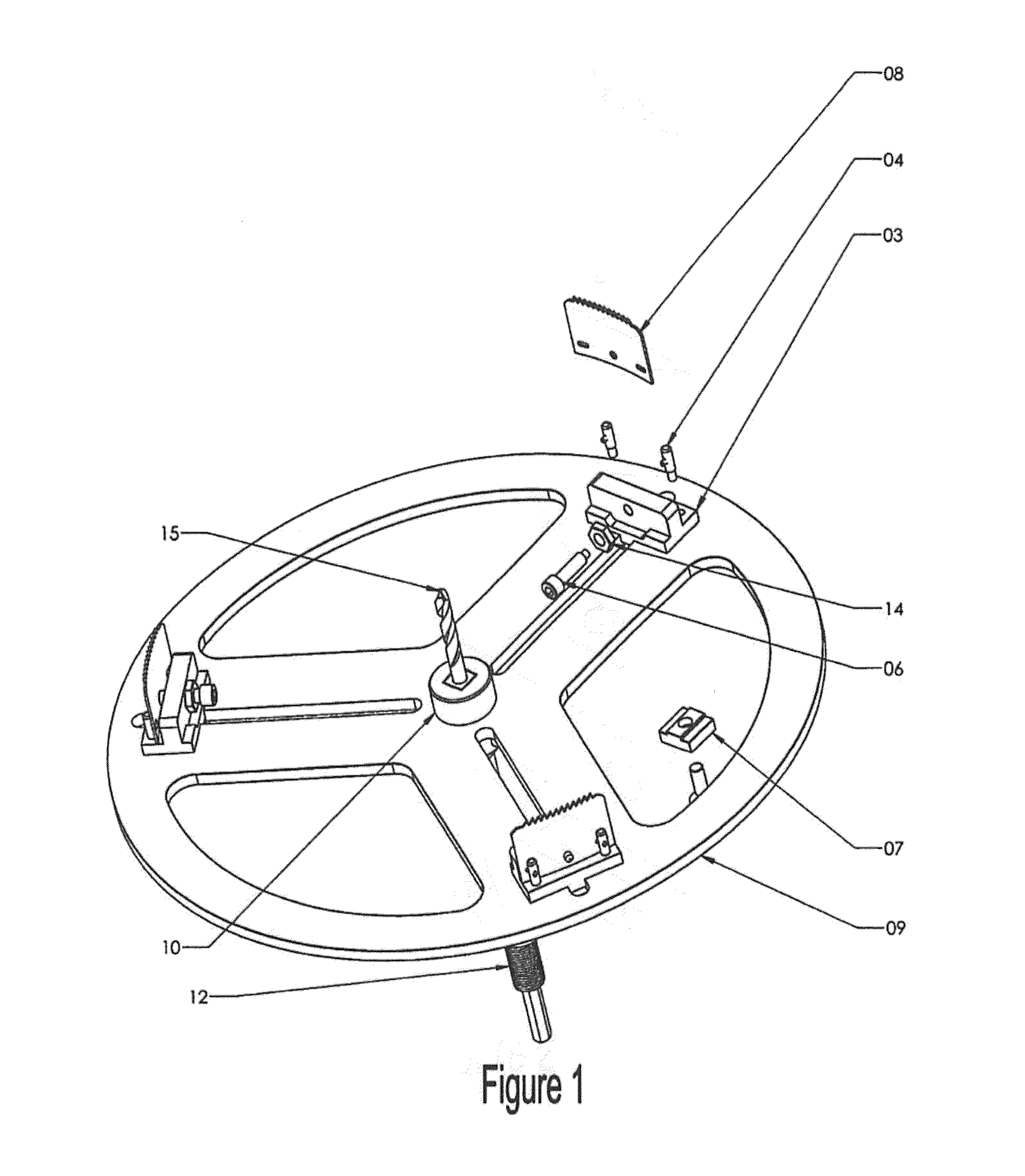
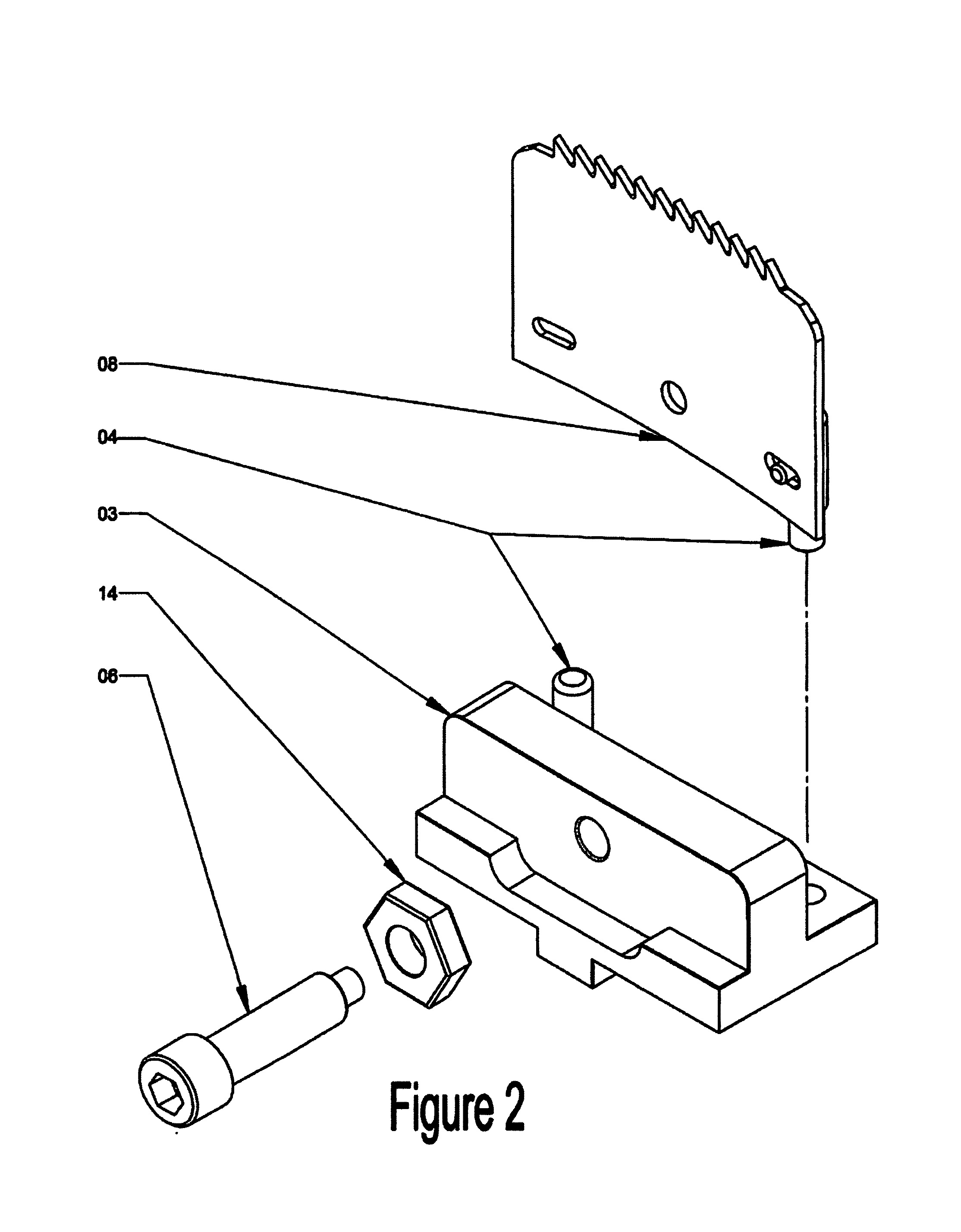
[0014]There are separate blade holder assemblies to which each of the blades or cutting members are attached. This blade holder assembly is key to the functioning of the preferred embodiment of the invention. The blade holder assembly provides three key functions: 1) it supports the blade 2) it enables changing the position of the blade along the radius of the hole cutter for cutting different size holes 3) it provides for adjusting the arc of the blade or cutting member to match those of the given diameter hole to be cut. Additionally the design of the blade holder assembly enables quick removal and replacement of the cutting members.
[0015]There is a separate detachable tool that provides a way to quickly determine and position each of the blades the same distance from the drive shaft of the apparatus. With the use of this detachable cutting radius gauge the overall design of the hole cutting apparatus is simplified without detracting from its performance.
[0016]The hole cutter can be used for cutting holes in sheet materials or boards of varying diameters with those diameters set by the operator. Instead of needing multiple hole saws for different size holes a single adjustable hole cutter can be used instead. Using multiple sections of blade material instead of a continuous band of teeth greatly reduces the power required to rotate the hole cutter and cut the material so a less powerful and hand held drill can be used to cut larger diameter holes than would otherwise be possible.

Problems solved by technology

The larger the hole the less likely that a fixed size hole saw exists in the size needed, and the cost for individual custom made hole saws can be prohibitive.
At the same time there are materials which include ceramic tiles and sheet metal that cannot be readily cut with the prior art designs of adjustable hole cutters.
With a material such as thin sheet metal the point of the prior art cutting blade will puncture the metal at one point in the circumference of the hole being cut and then the drill will not have sufficient power to continue the cutting operation.
With ceramic materials such as with floor tile the contact area of the blade tip or edge is too small for effective cutting regardless of the blade material composition or design.
These designs are very difficult and potentially hazardous to use without an exterior ball bearing mounted shield to support the hole cutter and keep it perpendicular to the work surface unless it is used in a stationary pillar type electric drill press.
The shield adds expense and requires more working space than an adjustable hole cutter without the shield.
When using a longer blade section with an adjustable hole cutter there arises a problem with the need to have a different arc of the blade or for different diameter holes.
The longer the blade segment used, or the smaller the diameter of the hole being cut, or the more difficult the material is to cut, as with thin sheet metal, the greater the need to have the arc of the blade match the arc of the circumference of the hole to be cut.

Method used


Image

  • Adjustable hole cutters
  • Adjustable hole cutters
  • Adjustable hole cutters

Examples


Embodiment Construction

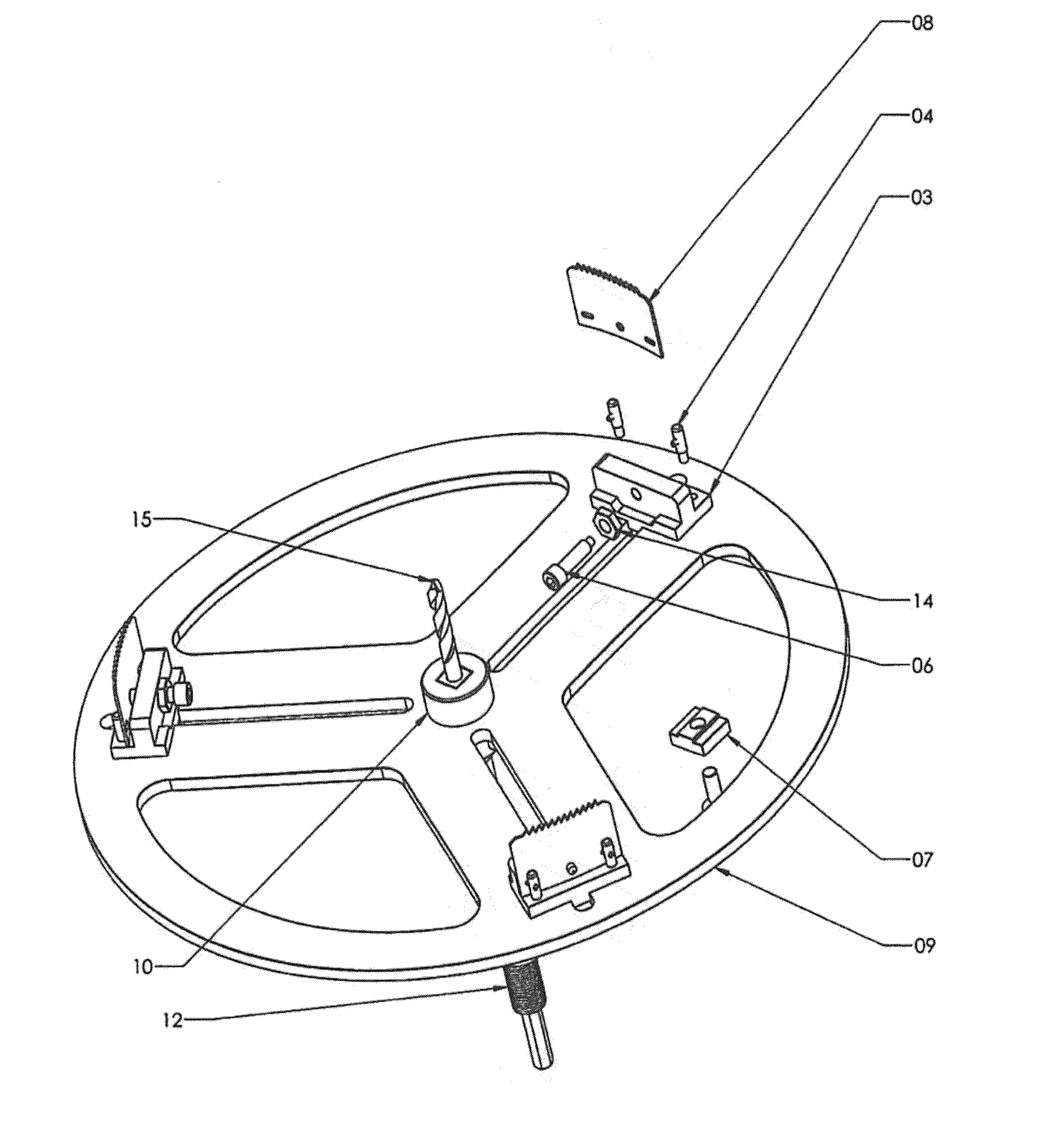
[0028]Referring to FIG. 1, the present invention is a hole cutting apparatus configured to be attached to a rotating portion of a power drill. The power drill may be substituted by other well-known devices configured for receiving and rotating other well known apparatus performing rotating operations. The apparatus shown in FIG. 1 is axially attached via a shaft which functions as an arbor drive shaft 12 which may have a hexagonal shape to retain it in a rigid manner in a three jaw clamping device attached to the power drill. The arbor drive shaft 12 may have other configurations as are well known in the art for transmitting torque to its rotational axis. From the top side of the arbor shaft extends a pilot drill bit 15, which is in axial alignment with the arbor drive shaft 12.

[0029]Along the radiating slots are circumferentially arrayed and attached blade holder assemblies 03 each with a cutting member 08, which are configured to gradually remove material from a work piece while k...


PUM

PropertyMeasurementUnit
radiusaaaaaaaaaa
diameteraaaaaaaaaa
radiusaaaaaaaaaa

Abstract

An adjustable hole cutter for cutting a hole with a predetermined diameter in sheet or panel material includes a blade holder that moves along a track or slot to alter a diameter of the cut hole; a blade arc adjuster coupled to the blade holder; and one or more replaceable blade segments coupled to the blade holder.

Description

FIELD OF INVENTION[0001]The present invention relates to adjustable hole cutters.BACKGROUND OF INVENTION[0002]In many construction, installation, and fabrication and industrial tasks a hole needs to be made in a ceiling, wall, flooring, or panel, for passage of wiring, piping, or ducting, for installing a fixture, or other purpose. The larger the hole the less likely that a fixed size hole saw exists in the size needed, and the cost for individual custom made hole saws can be prohibitive. At the same time there are materials which include ceramic tiles and sheet metal that cannot be readily cut with the prior art designs of adjustable hole cutters.[0003]With a material such as thin sheet metal the point of the prior art cutting blade will puncture the metal at one point in the circumference of the hole being cut and then the drill will not have sufficient power to continue the cutting operation. With ceramic materials such as with floor tile the contact area of the blade tip or edge...

Claims


Application Information

Patent Timeline
Patent Type & Authority Patents(United States)
IPC IPC(8): B23B51/05B28D1/04
CPCB23B51/05B28D1/041B23B2251/606B23B2251/54Y10T408/885Y10T408/88Y10T408/895Y10T408/50Y10T408/86Y10T408/21B23B51/0411
Inventor STENMAN, BRUCE, WINTER
Owner STENMAN BRUCE WINTER
Why Eureka
Try Eureka