
Allograft bone plugs, systems and techniques

a technology of bone screws and plugs, applied in the field of orthopaedics, can solve the problems of screw insertion and revision, screw slipping, and screw slipping, so as to improve the holding strength and purchase of screws, improve the fit, and improve the holding strength of screws, pins or dowels.

Active Publication Date: 2014-09-23
DEPUY SYNTHES PROD INC
View PDF274 Cites 28 Cited by
  • Summary
  • Abstract
  • Description
  • Claims
  • Application Information

AI Technical Summary

Benefits of technology

The present invention provides a system, device, instruments, and methods for improving the holding strength and purchase of a screw in bone tissue. The invention is a longitudinally elongated member that is inserted into a preformed hole and has a distal end, a proximal end, and a longitudinal axis. The implant can increase the holding strength of the screw, pin, or dowel, and can also fill voids in bone tissue or improve the fit between instruments or implants. The implant is made of a flexible, elastic, and floppy material, such as at least partially demineralized bone tissue. Overall, the invention improves the stability and securement of bone screws, pins, and dowells in bone tissue, and provides a better fit between instruments or implants.

Problems solved by technology

However, the presence of osteoporotic bone, fractured, damaged or diseased bone may reduce the effective purchase between a bone screw and the interior of the bone with which the screw interfaces.
Further, previous screw insertion and / or an attempt at inserting a larger diameter screw may further complicate screw insertion and revision, and increase the incidence of the screw breaching the bone or the screw “stripping”.
In addition, prior attempts involved implanting foreign substances into the patient's bone.
One problem associated with pedicle screw fixation is loss of purchase between the bone screw and the patient's vertebrae.
Another problem associated with screw fixation is loss of holding strength of a bone screw in bone, particularly a bone screw in a vertebra.
Toggling of the screw in bone is another problem that may lead to loss of purchase and holding strength.

Method used


Image

  • Allograft bone plugs, systems and techniques
  • Allograft bone plugs, systems and techniques
  • Allograft bone plugs, systems and techniques

Examples


Embodiment Construction

[0044]Certain terminology is used in the following description for convenience only and is not limiting. The words “right”, “left”, “lower”, “upper”, “top” and “bottom” designate directions in the drawings to which reference is made. The words “inwardly” and “outwardly” refer to directions toward and away from, respectively, the geometric center of the implant and designated parts thereof. The words, “anterior”, “posterior”, “superior”, “inferior”, “medial”, and “lateral” and related words and / or phrases designate preferred positions and orientations in the human body to which reference is made and are not meant to be limiting. The terminology includes the above-listed words, derivatives thereof and words of similar import.

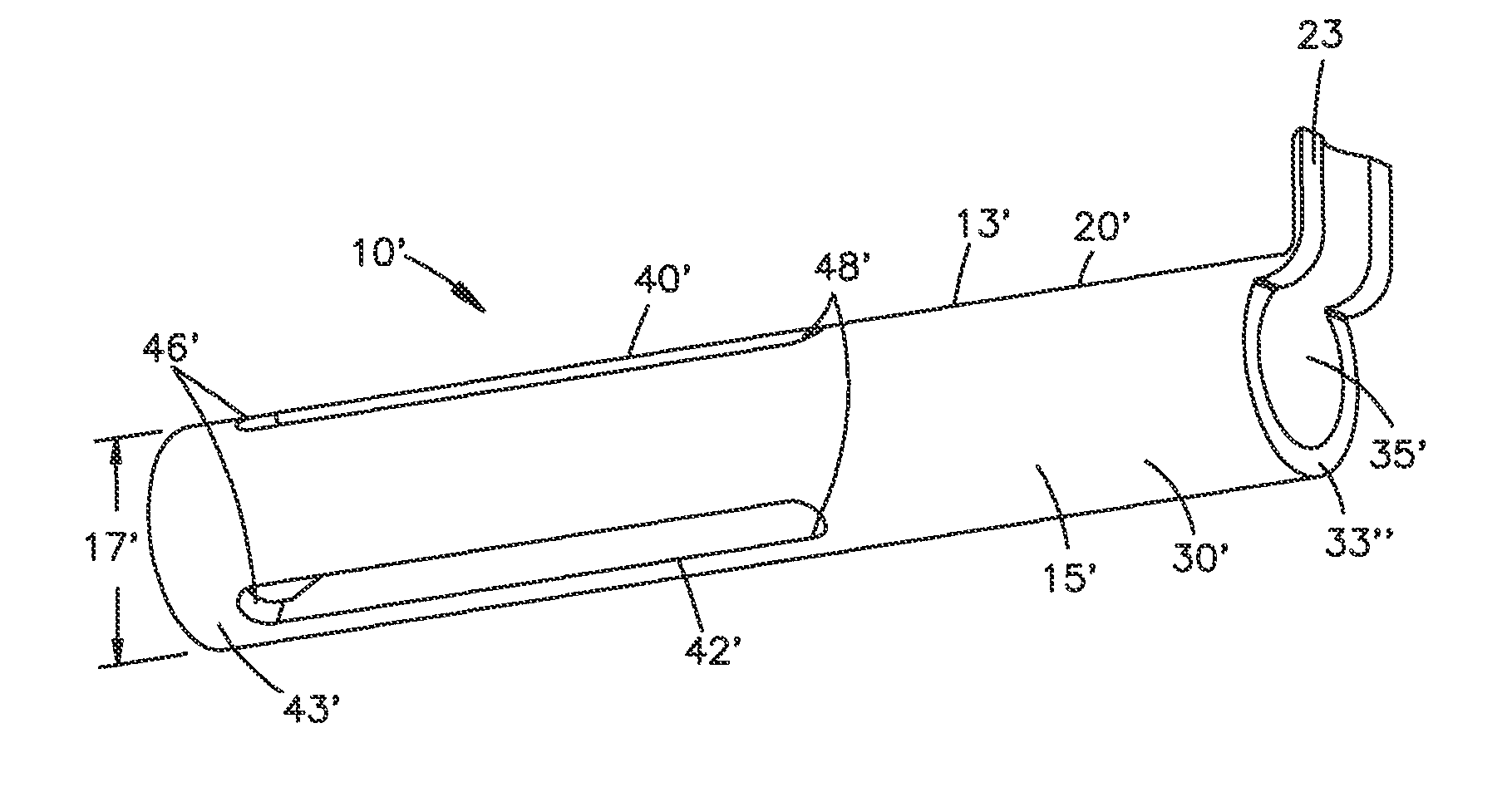
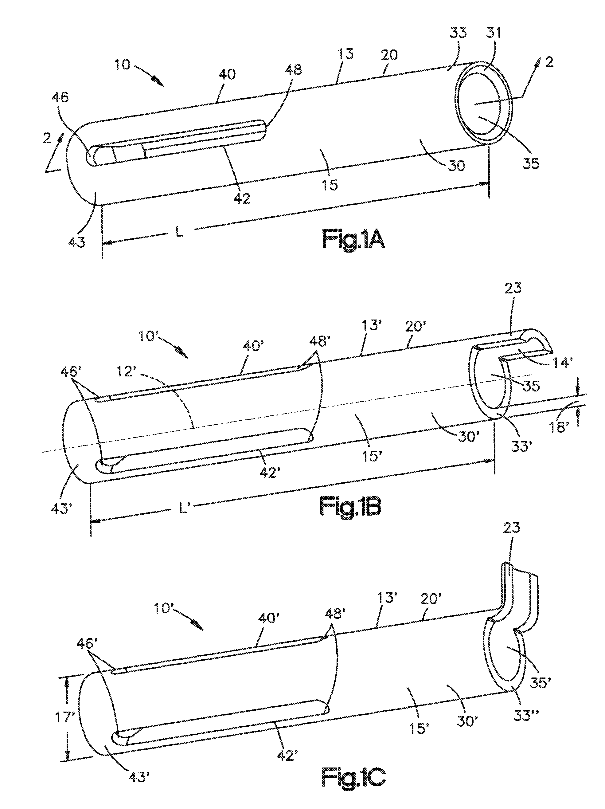
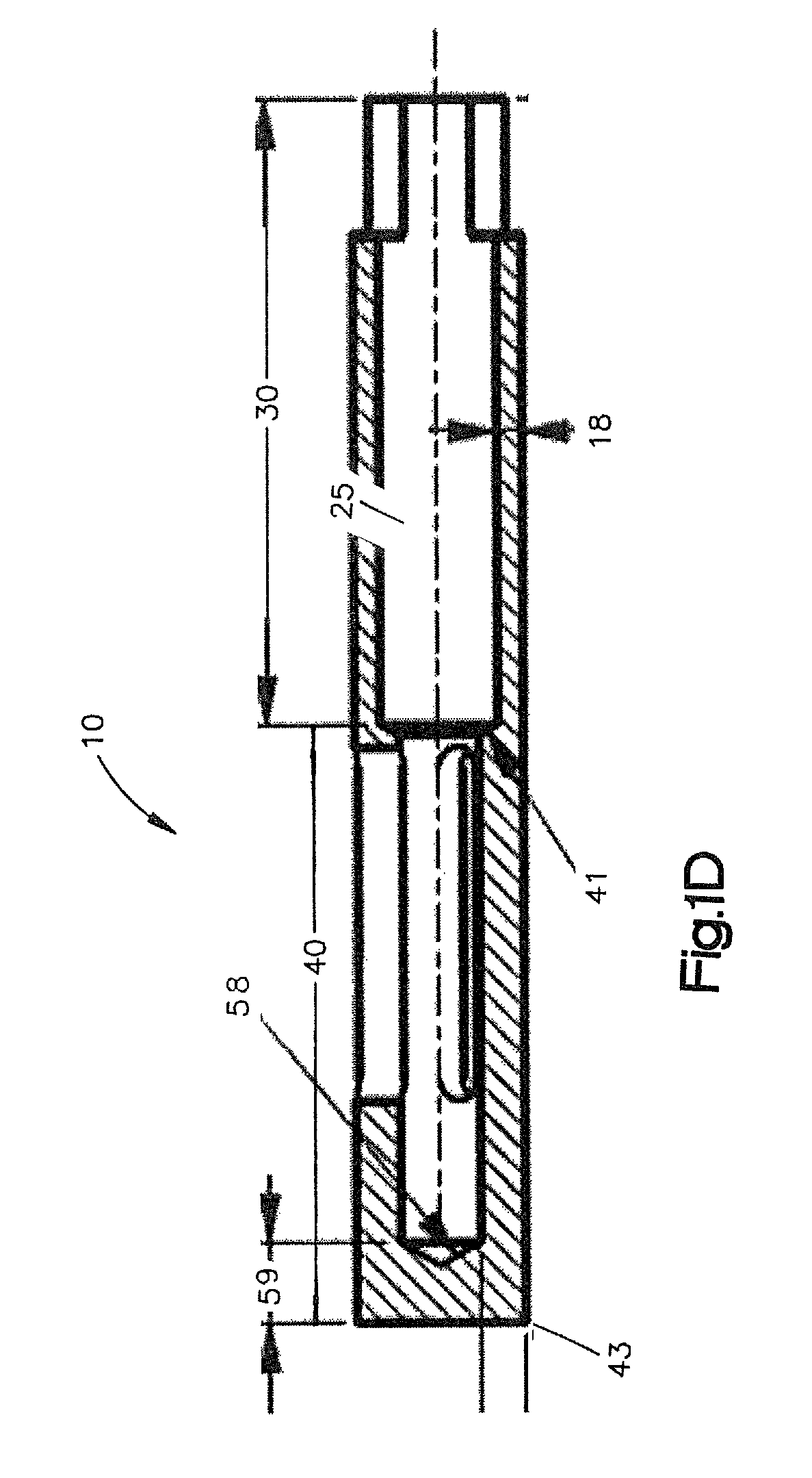
[0045]Bone implant, bone augmentation device or bone protection device 10 (also referred to as a bone plug or shim) in the form of longitudinally elongated member for positioning between shaft of a screw and surrounding bone tissue to increase the holding strength...


PUM

PropertyMeasurementUnit
thicknessaaaaaaaaaa
thicknessaaaaaaaaaa
thicknessaaaaaaaaaa

Abstract

The present invention provides a system, device, instruments and methods for inserting and / or improving the holding strength and purchase of a bone screw, bone pin, or bone dowel in bone. Embodiments include monolithic allograft tissue forms, multi-piece allograft tissue forms, distally expandable portions, partially and fully demineralized portions, and flexible connecting portions. Advantages of the allograft tissue forms of the present invention include improved pedicle screw blackout strength and improved filling of bone voids. Methods for making and instruments and techniques for inserting the augmentation device, system and screws or pins are also disclosed.

Description

CROSS REFERENCE TO RELATED APPLICATIONS[0001]This application is a continuation-in-part of and claims priority to International Application No. PCT / US2009 / 048055, filed Jun. 19, 2009, entitled “Bone Screw Purchase Augmentation Implants, Systems and Techniques,” which claims priority to U.S. Provisional Patent Application No. 61 / 073,998, filed Jun. 19, 2008, entitled “Screw Augmentation Anchor” and to U.S. Provisional Patent Application No. 61 / 106,862, filed Oct. 20, 2008, entitled “Pedicle Screw Purchase Augmentation Techniques and Implants.” The contents of these related applications are hereby incorporated by reference in their entirety.FIELD OF THE INVENTION[0002]The invention relates generally to orthopedics. More specifically, the present invention relates to a device, instrumentation and method for filling bone voids and for increasing the purchase and holding strength of screws, particularly bone screws in bone, more particularly, bone screws in vertebrae.BACKGROUND OF THE IN...

Claims


Application Information

Patent Timeline
Patent Type & Authority Patents(United States)
IPC IPC(8): A61F2/28A61B17/04A61B17/68F16B13/00
CPCA61B17/686F16B2013/009A61B17/68A61B17/70A61B17/86A61F2/28
Inventor KALE, SHREEDHARCHIEN, DENNISDELURIO, ROBERTCOMPTON, CURTIS
Owner DEPUY SYNTHES PROD INC
Learn More