Eureka AIR delivers breakthrough ideas for toughest innovation challenges, trusted by R&D personnel around the world.

Serial connected fuel cell stack module assembly

a fuel cell and module technology, applied in the direction of cell components, sustainable manufacturing/processing, cell components, etc., can solve the problems of failure risk of fuel cell stacks, and increase with the number of cells and the size of the area, so as to achieve simple mechanical structure, bending, and reduce the effect of bending

Inactive Publication Date: 2014-09-23
HALDOR TOPSOE AS
View PDF9 Cites 3 Cited by
  • Summary
  • Abstract
  • Description
  • Claims
  • Application Information

AI Technical Summary

Benefits of technology

[0015]An object of the invention is also to provide a SOFC stack assembly which reduces the necessity of heat exchangers for cooling and heating.
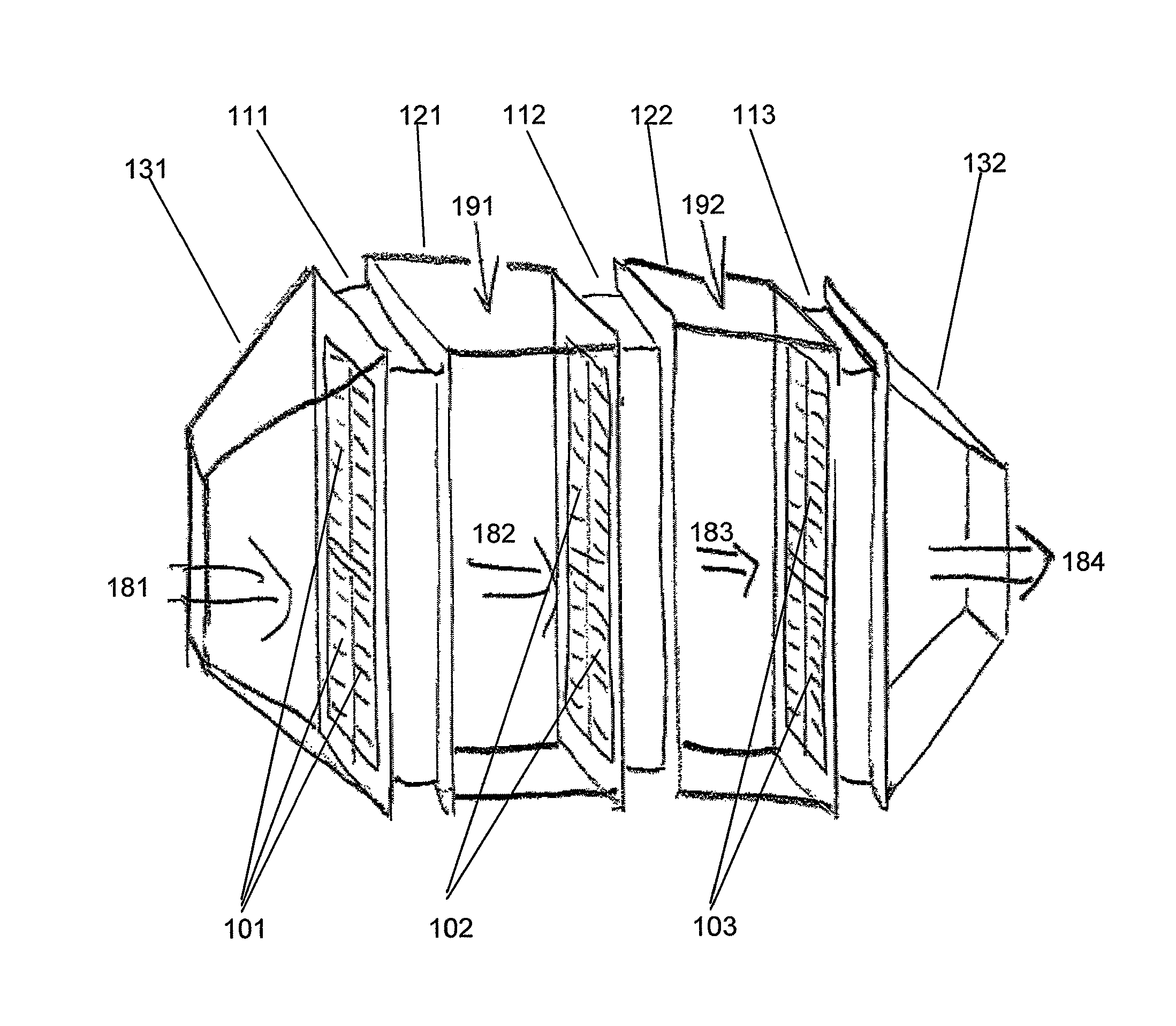
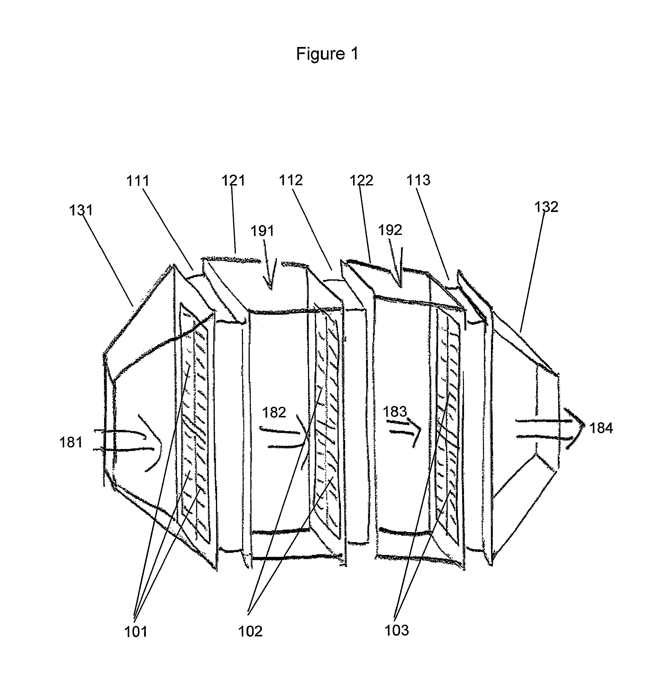
[0029]4. Balance-of-plant components, like the high-temperature heat exchanger for cathode air preheating, can be integrated at the ends of the duct formed by the serially connected stacks, further adding to a compact and cost-effective mechanical structure.

Problems solved by technology

There is a feasible limit to the size of stacks, to the area of each cell as well as to the number of cells which are assembled.
The failure risk of a fuel cell stack increases with the number of cells and the size of the area.
US 2006 / 0172176 A1 and U.S. Pat. No. 6,033,794 disclose examples of serially connected fuel cell stacks, but not how to realize the connection.
In spite of the presented known solutions to the connection problem of several fuel cell stacks, all of them have some of the inherent problems:Though several stacks are connected in single modules, still the cathode gas manifolding has not been equally simplified.When several stacks or several modules are connected in series, an extensive channelling / piping is necessary to connect to cathode and anode gas.Connecting several stacks to increase effect also increases the supply system demand (heat exchangers for cooling and pre-heating).Relative high temperature fuel cells, such as Solid Oxide Fuel Cell stacks has relative long start-up and shut-down periods.SOFC assemblies of several stacks with relative large effect output, have a low flexibility towards varying the effect output.

Method used


Image

  • Serial connected fuel cell stack module assembly
  • Serial connected fuel cell stack module assembly
  • Serial connected fuel cell stack module assembly

Examples


Embodiment Construction

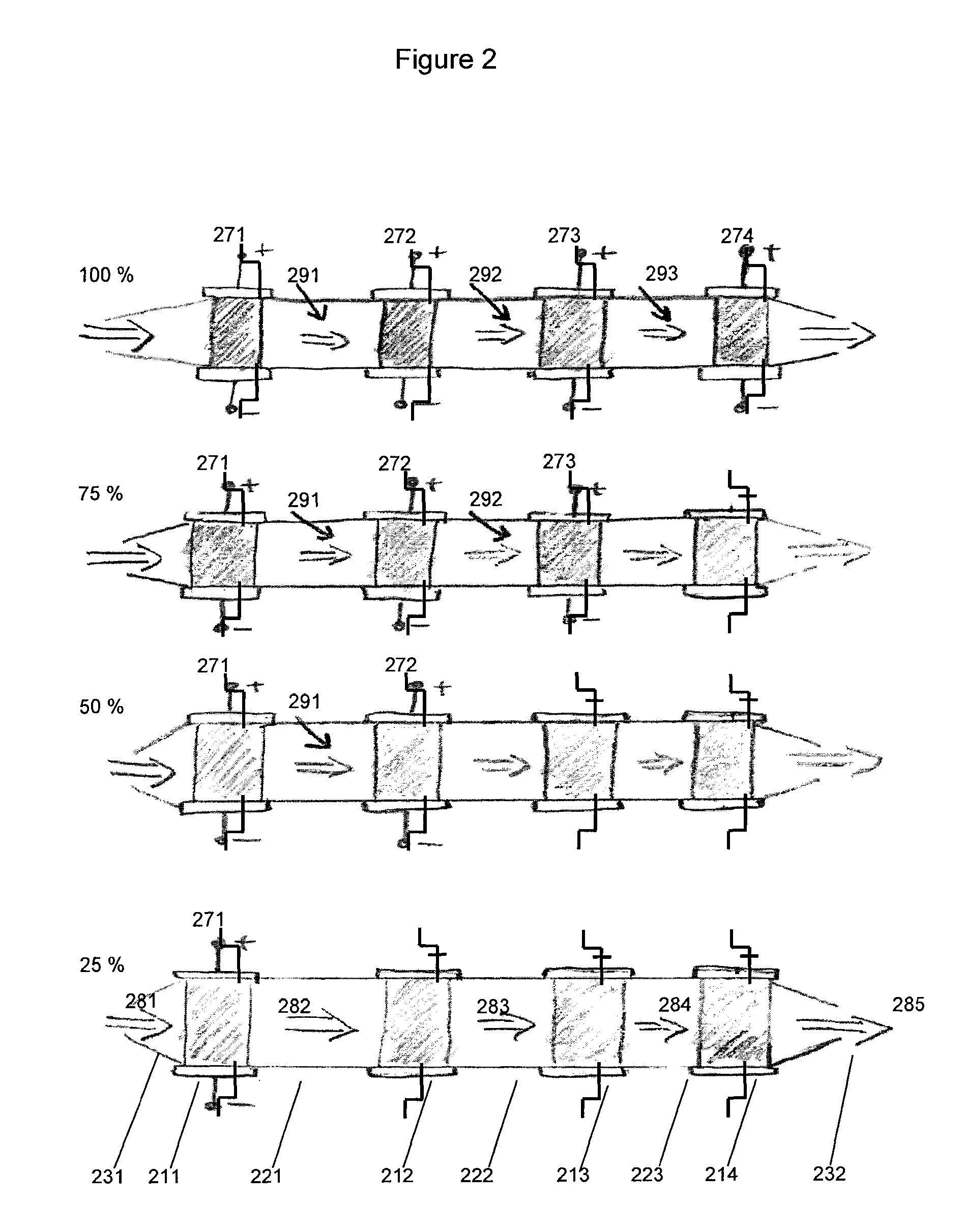
[0054]Position number overview:[0055]101: Fuel cell stacks of the first primary stack module.[0056]102: Fuel cell stacks of the second secondary stack module.[0057]103: Fuel cell stacks of the third secondary stack module.[0058]111, 211: First primary fuel cell stack module.[0059]112, 212: Second secondary fuel cell stack module.[0060]113, 213: Third secondary fuel cell stack module.[0061]214: Fourth secondary fuel cell stack module.[0062]121, 221: First intermediate channel.[0063]122, 222: Second intermediate channel.[0064]223: Third intermediate channel.[0065]131, 231: First common cathode gas inlet side manifold (of the first stack module).[0066]132, 232: Second common cathode gas outlet side manifold (of the third / fourth stack module).[0067]181, 281: Inlet cathode gas for the first, primary stack module.[0068]182, 282: Cathode gas stream from the first, primary stack module to the second, secondary stack module.[0069]183, 283: Cathode gas stream from the second, secondary stack ...


PUM

PropertyMeasurementUnit
temperatureaaaaaaaaaa
voltageaaaaaaaaaa
sizeaaaaaaaaaa

Abstract

A large, scalable SOFC system based on modules, which may be connected in series on the cathode gas side. The fuel cell stacks are aligned side by side and assembled into a stack module with cathode inlets on one face of the module and the cathode outlets on the other face of the module. The stack modules are serially connected in a simple manner by placing the stack modules one after the other, so that the outlet face of the first module faces the inlet face of the second module and so on. In the chamber between two stack modules, the air is cooled for example by addition of cold quench air or by a heat exchanger. This offers compactness, simple stack / system interface and improved system performance. The modules are designed for manufacturability, well-balanced heat management and high fuel utilization.

Description

BACKGROUND OF THE INVENTION[0001]1. Field of the Invention[0002]The invention relates to a modular connection of fuel cell stacks, more specifically to stack modules with a serial connection of the cathode gas inlets and outlets, more specifically to stack modules each having one inlet and one outlet common cathode gas side manifold for all the fuel cells in a module, in particular for Solid Oxide Fuel Cell (SOFC) stacks.[0003]2. Description of the Related Art[0004]The electro-chemical reactions and the function of a fuel cell is not the essence of the present invention, thus this is not explained in greater detail here, but considered known to a person skilled in the art.[0005]To increase the voltage produced by the SOFC, several cell units are assembled to form a stack and are linked together by interconnects. These layers of the stack are sealed together by means of a gas tight and temperature resistant seal, such as glass, along some or all edges. There is a feasible limit to th...

Claims


Application Information

Patent Timeline
Patent Type & Authority Patents(United States)
IPC IPC(8): H01M8/04H01M8/12H01M8/24
CPCH01M8/249H01M8/2485H01M8/2425H01M8/04089H01M8/04014H01M2008/1293Y02E60/50Y02E60/525H01M8/2457H01M8/2484Y02P70/50
Inventor ERIKSTRUP, NIELSUSTERUD, HARALDDANO, SUNE
Owner HALDOR TOPSOE AS
Why Eureka
Eureka Blog
Learn More