Spring washer and a bearing block including a spring washer

a technology of bearing block and spring washer, which is applied in the direction of bearings, shafts, linear movement shafts, etc., can solve the problems of increasing vibration, bearing running unsteadily, and likely to suffer fretting wear, and achieves the effect of simple and cost-effective manufacturing

Active Publication Date: 2014-09-30
MAXON MOTOR AG
View PDF23 Cites 18 Cited by
  • Summary
  • Abstract
  • Description
  • Claims
  • Application Information

AI Technical Summary

Benefits of technology

[0019]In another particularly preferred embodiment of the present invention, the spring washer is manufactured by means of stamp-bending. This makes an extremely simple and cost-effective manufacturing of the spring washer according to the invention possible.
[0020]For a stable connection of the inner and outer ring and for the most symmetric spring effect possible, the connection ro

Problems solved by technology

This play results in increased vibrations, especially at high rotational speeds.
Because of this the bearing runs unsteadily, and in case of longer operations fretting wear is likely to occur due to the friction between the balls and the bearing rings.
The axial preload by means of conventional compression coil springs has the disadvantage that compression coil springs are comparatively long and therefore require a large installation space.
Therefore, components which are referred to as spring washers have already been used for a long time for axial preloading.
Those corrugated spring washers have the disadvantage that in the course of time creeping occurs which is caused by a plastic deformation of the corrugated outer

Method used


Image

  • Spring washer and a bearing block including a spring washer
  • Spring washer and a bearing block including a spring washer
  • Spring washer and a bearing block including a spring washer

Examples


first embodiment

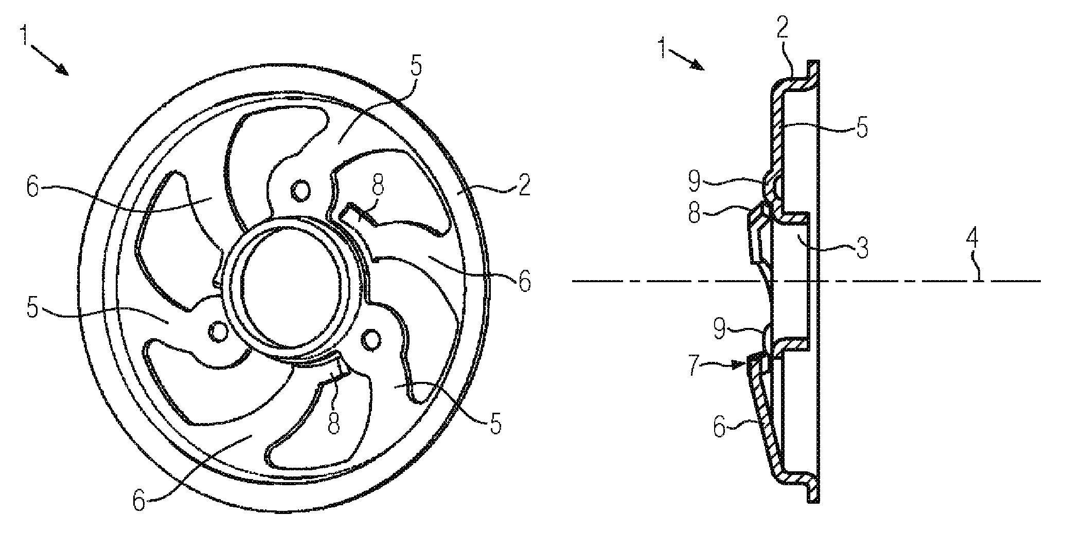
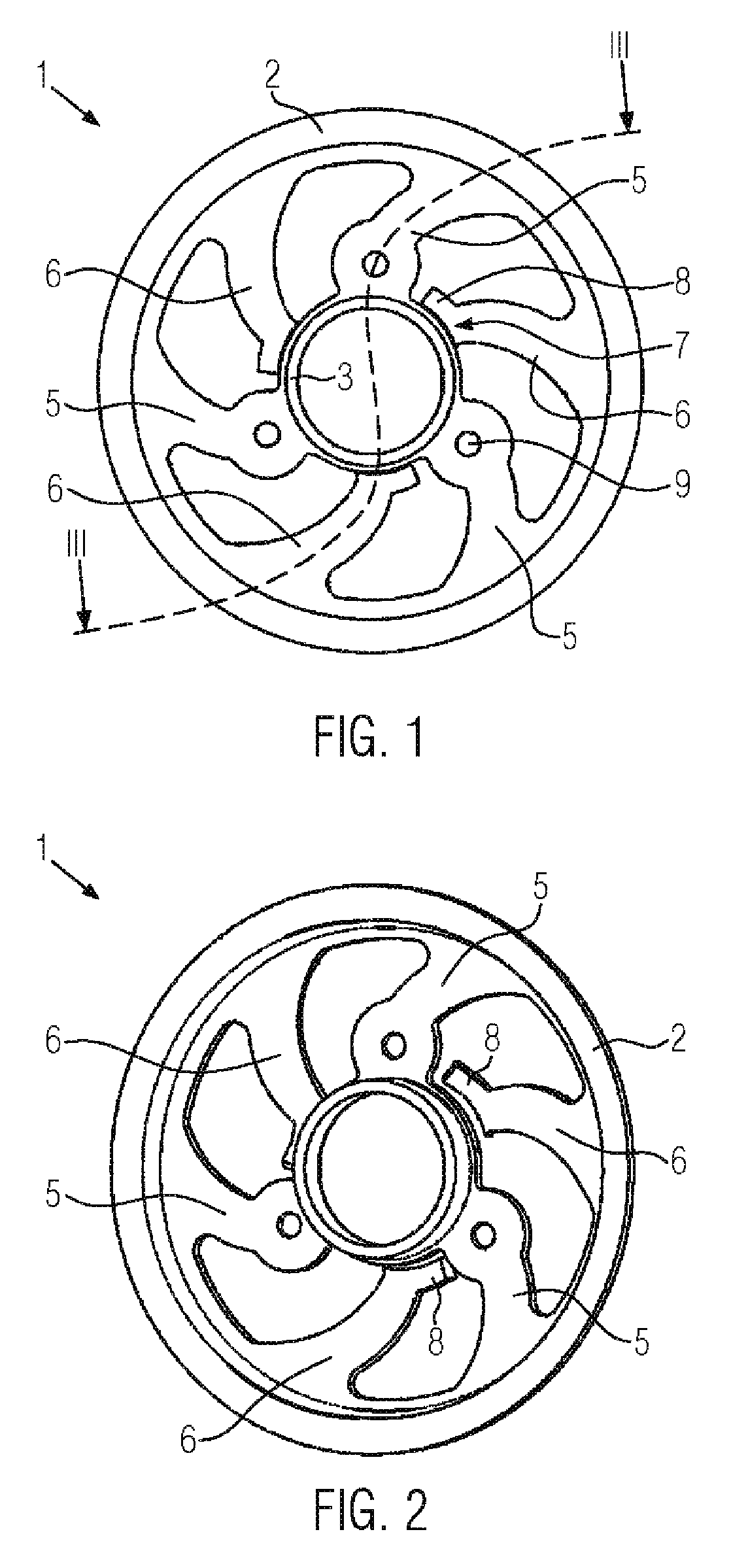
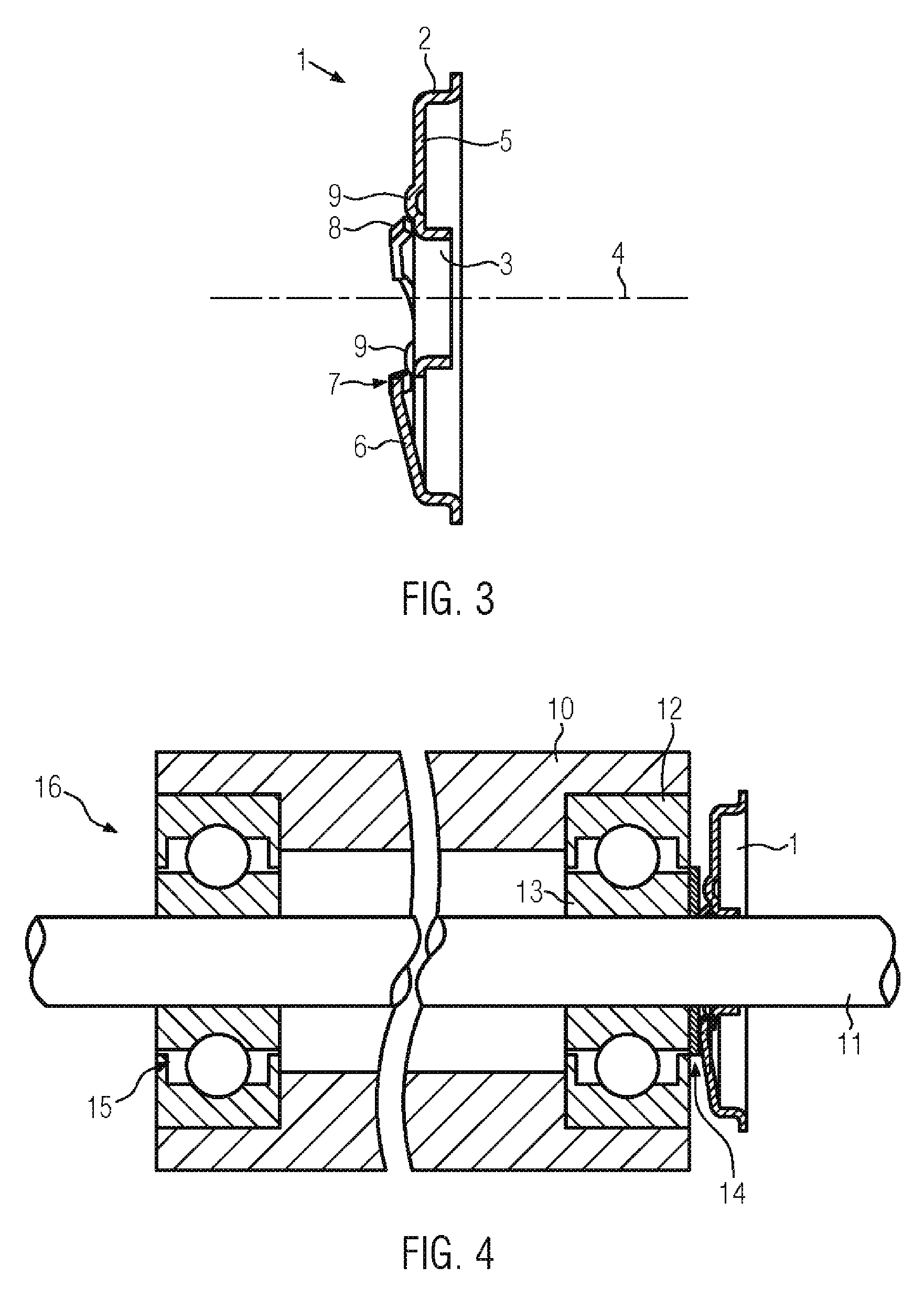
[0037]FIGS. 1 to 3 display an inventive spring washer 1. The spring washer 1 consists of an outer ring 2 and an inner ring 3, which are concentrically arranged and are connected through three connection rods 5. As shown in FIG. 3, the connection rods 5 are in-plane. Both of the rings, i.e. the outer and inner ring, are formed as short cylindrical tube sections for reasons of stability. Moreover, the outer rim of the outer ring is bent outwards to an angle of 90 degrees, whereby the stability of the component is further increased. The displayed connection rods 5 are equally distributed along the perimeter of the spring washer 1 and run slightly spirally shaped from the inner ring 3 to the outer ring 2.

[0038]Between two fixed connection rods 5 there is additionally arranged one cantilevered resilient rod 6 which extends from the outer ring inwards and also is spirally shaped. At the inner ring 3, the cantilevered rods 6 have a free end 7 on which an extension 8 runs alongside the inne...

second embodiment

[0041]an inventive spring washer 1 is displayed in FIGS. 5 to 7. Here the cantilevered rods 6 are not fixed to the outer ring 2, but to the inner ring 3. The free ends 7 of the cantilevered rods 6 are thus arranged at the outer ring 2 of the spring washer 1. As shown in FIG. 7, the cantilevered rods 6 in this application example are also axially bent up such that their free ends 7 have an axial offset to the plane of the fixed connection rods 5 in the case of the stress-relieved state of the spring washer 1. In this embodiment the resilient connection rods 5 and the resilient cantilevered rods 6 also run in a slight spiral shape.

[0042]FIG. 8 displays a bearing block 16, similar to the bearing block from FIG. 4, wherein the axial preload of the floating bearing is achieved by means of a spring washer in compliance with the embodiment in FIGS. 5 to 7. In the case of the bearing block 16 displayed in FIG. 8, the inner bearing ring 13 of the right-hand floating bearing is also fixed to ...


PUM


Abstract

A spring washer is disclosed for axially preloading anti-friction bearings. The spring washer can include an outer ring and an inner ring that is coaxially arranged with respect to the outer ring. An axis is defined by the two rings. Outer and inner rings are connected through several resilient connection rods. Resilient cantilevered rods can be provided which extend from one of the rings in between the connection rods and which have a free end at the opposite positioned ring. Thereby, the cantilevered rods can be axially bent up such that the free end has an axial offset.

Description

FIELD[0001]The invention relates to a spring washer and a bearing block. Such a spring washer is used for the axial preload of anti-friction bearings. The spring washer comprises an outer ring as well as an inner ring that is coaxial to the outer ring. An axis is defined by means of these two rings. The outer and inner rings are connected through several resilient connection rods.BACKGROUND INFORMATION[0002]Such spring washers are used for the axial preload of anti-friction bearings of a bearing block. Such a bearing block commonly comprises a stationary component, a shaft and an anti-friction bearing that is located in between. An outer bearing ring of the anti-friction bearing is fixed to the aforementioned component, and an inner bearing ring of the anti-friction bearing is fixed to the shaft.[0003]It is generally known from the prior art to preload anti-friction bearings axially by means of spring washers or conventional coil springs. The axial preload is necessary for numerous ...

Claims


Application Information

Patent Timeline
IPC IPC(8): F16C25/08F16C1/18F16C27/00F16F1/32
CPCF16C25/083F16F1/326F16C2380/26
Inventor TEIMEL, ARNOLD
Owner MAXON MOTOR AG
Why Eureka
Try Eureka