Method for locating an optical marker in a diffusing medium

a technology of optical markers and diffusing mediums, applied in the field of optical imaging, can solve the problems of inability to detect specific fluorescence signals, limited fluorescence optical imaging, and inability to accurately detect specific signals,

Active Publication Date: 2014-09-30
COMMISSARIAT A LENERGIE ATOMIQUE ET AUX ENERGIES ALTERNATIVES
View PDF43 Cites 19 Cited by
  • Summary
  • Abstract
  • Description
  • Claims
  • Application Information

AI Technical Summary

Benefits of technology

[0051]During the step of processing the array X comprising the measured time data, the latter being also called acquisitions, A and S can be determined by minimizing a cost function F, wherein this function can be:

Problems solved by technology

The fluorescence optical imaging (with an injection of the specific fluorophore) is currently limited to “small animal” applications due to the lack of markers adapted and injectable to human, and the tissue auto-fluorescence problem that arises for depth detection.
But the specific signal to be detected weakens with depth, mainly because of the tissue absorption and diffusion, and is confronted with a spurious signal which disturbs the detection.
Furthermore, filtering the excitation light is not always perfect and a little excitation light can pass through the fluorescent filter intended to remove it and is added to the measured signal.
Both phenomena, auto-fluorescence peculiar to tissues and spurious signal due to the system, are phenomena which interfere and distort the fluorescence measurement.
A limitation of these techniques is the necessity to find a reference area without significant fluorescence and to reproduce similar acquisition conditions.
This technique only enables a two dimension image to be carried out, but does not enable information on the depth localization of species of interest to be accessed.
This technique is obviously time consuming (it requires to carry out a measurement without fluorescent inclusion and then a measurement with fluorescent inclusion) and is delicate to implement.
Generally, there is therefore the problem of finding a new method, not requiring implementing a spectral technique, that can be quickly performed (in view of in vivo application) and enabling the different contributions of luminous sources to be differentiated, and in particular the contributions of fluorescent sources and spurious sources, by resorting to a time resolved fluorescence technique.
There is also the problem of finding a new device, enabling to implement such a method.

Method used


Image

  • Method for locating an optical marker in a diffusing medium
  • Method for locating an optical marker in a diffusing medium
  • Method for locating an optical marker in a diffusing medium

Examples


Embodiment Construction

[0027]An embodiment first relates to a method for processing data relating to at least one optical marker in a diffusing medium, wherein:

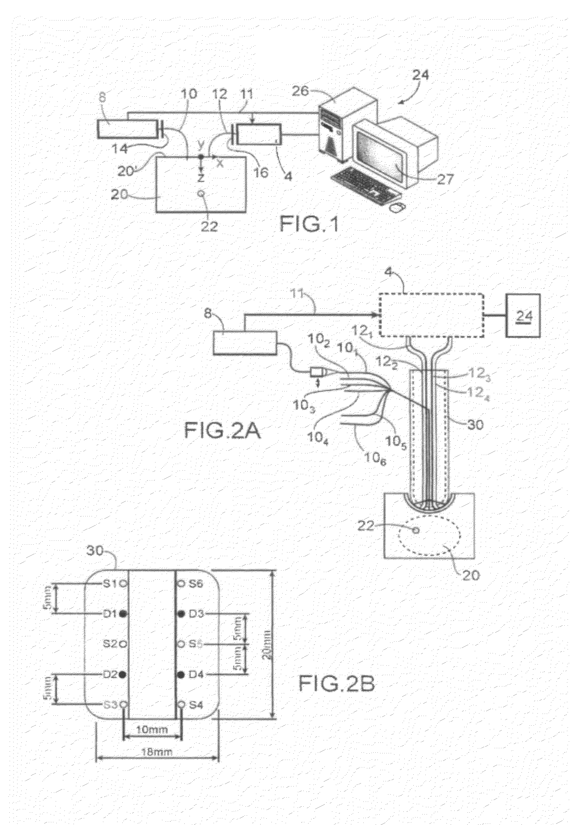
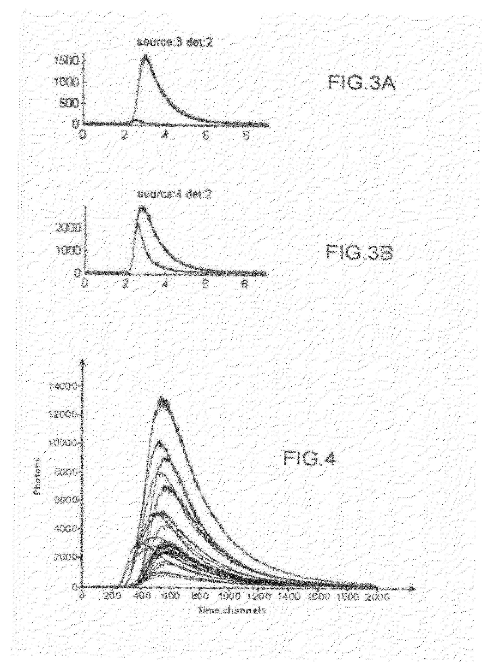
[0028]a) at least one acquisition of a time resolved optical signal is performed, this signal resulting from an excitation of the medium using a pulsed radiation source, each acquisition including on the one hand a component of interest, due to said marker, and on the other hand a spurious component,

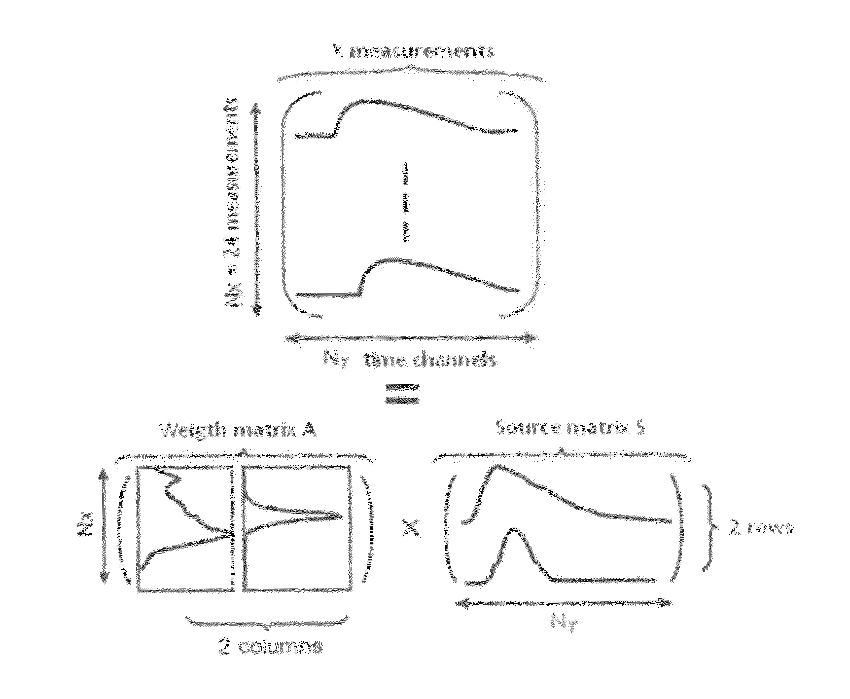
[0029]b) a matrix X is made from each acquisition performed in step a).

[0030]Then, the data of said matrix X can be processed by factorizing this matrix into a product of two non-negative matrices A and S.

[0031]It is then possible to extract, or to determine or calculate or identify, the contribution of one of said components to at least one of said acquisitions, from terms of the matrices A and S.

[0032]According to one embodiment, such a method can further include a step of calculating or determining or identifying or locating the position of at least ...


PUM

PropertyMeasurementUnit
wavelengthaaaaaaaaaa
distanceaaaaaaaaaa
distanceaaaaaaaaaa

Abstract

A method for locating at least one optical marker in a diffusing medium, the marker having at least one optical property different from the diffusing medium, wherein: a) a pulsed radiation interacts with the medium and the at least one optical marker, producing an optical signal, and at least one acquisition of data of the optical signal is performed, each acquisition including one or more time components of interest, due to the at least one marker, and a spurious component, due to the medium other than the at least one marker, b) a multidimensional array X is formed from the optical signal data of the at least one of the acquisitions, c) the array X is processed by factorization into a product of only two non-negative multidimensional arrays A and S, and d) at least one of the time components is extracted from the arrays A and S.

Description

TECHNICAL FIELD AND PRIOR ART[0001]This invention relates to the field of optical imaging, for example fluorescence imaging, in diffusing media and in particular the biological tissues. It implements time resolved optical methods.[0002]It is applicable in the medical field, in particular in the fluorescence diffuse optical tomography for determining the distribution of fluorescent particles, for example markers.[0003]The diffuse optical imaging, and in particular fluorescence imaging, offers the prospect of having non-invasive diagnostic systems thanks to the use of easy to use inexpensive non-ionizing radiations.[0004]In applications implementing fluorescence imaging, fluorescent markers are injected in the subject and bind to some specific molecules, for example cancer tumours. The area of interest is lighted at the optimum excitation wavelength of the fluorophore (chemical substance of a molecule capable of emitting the fluorescence light after excitation) and the fluorescent sig...

Claims


Application Information

Patent Timeline
Patent Type & Authority Patents(United States)
IPC IPC(8): G01N21/64A61B5/00G01N21/49
CPCA61B5/0073G01N21/6408G01N21/49G01N21/6456G01N21/6428G01N2021/6484
Inventor LAIDEVANT, AURELIEDINTEN, JEAN-MARCMONTCUQUET, ANNE-SOPHIE
Owner COMMISSARIAT A LENERGIE ATOMIQUE ET AUX ENERGIES ALTERNATIVES
Why Eureka
Try Eureka