Injector for a vacuum evaporation source

a vacuum evaporation source and injector technology, applied in vacuum evaporation coatings, chemical vapor deposition coatings, coatings, etc., can solve the problems of oxidized materials becoming cracked, clogging a part of the nozzle, and non-uniform spraying of vaporized materials on the panels, so as to avoid clogging of the nozzle.

Active Publication Date: 2014-10-14
RIBER
View PDF9 Cites 2 Cited by
  • Summary
  • Abstract
  • Description
  • Claims
  • Application Information

AI Technical Summary

Benefits of technology

[0012]One object of the present invention is to provide an injector...

Problems solved by technology

Because of the variations of temperature, the oxidized materials become cracked.
Some flakes of oxidized materials become detached from the wall of the injector and fall on the top face of the ...

Method used


Image

  • Injector for a vacuum evaporation source
  • Injector for a vacuum evaporation source
  • Injector for a vacuum evaporation source

Examples


Embodiment Construction

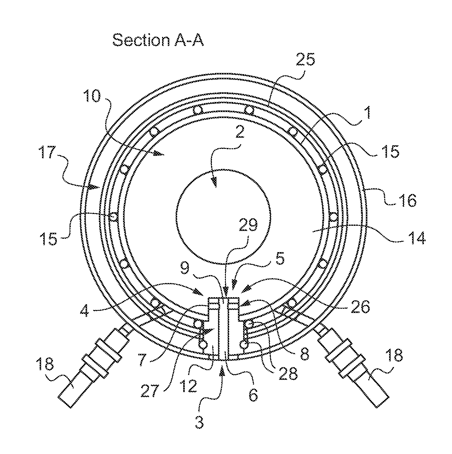
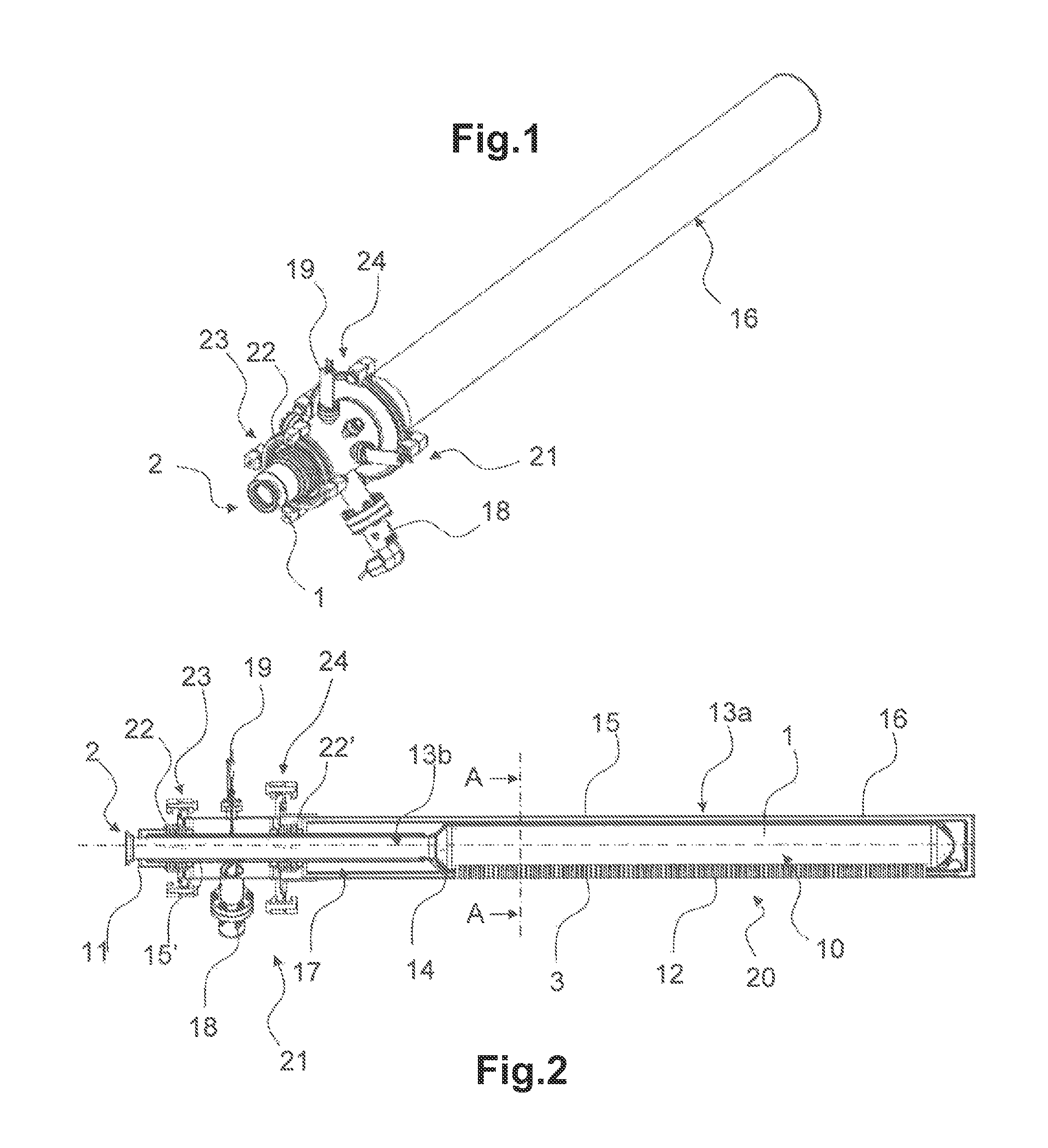
[0036]As illustrated in FIGS. 1 and 2, the injector comprises an injection duct 1 delimiting a first vacuum volume 10. The injection duct 1 extends longitudinally and has a tubular shape with a circular section.

[0037]The injection duct 1 comprises an inlet port 2 able to be connected to a vacuum evaporation source, and at least one nozzle 3 for diffusing the vaporized materials into a vacuum deposition chamber (not represented).

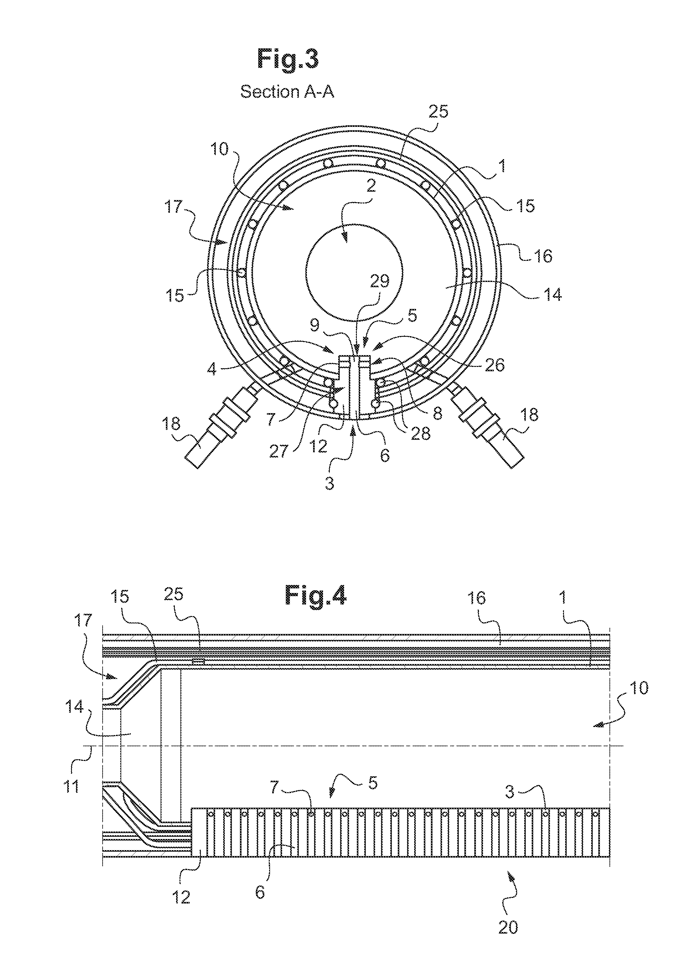
[0038]In the example of FIG. 4, the injection duct 1 comprises several nozzles 3 which are equidistant and aligned according to a longitudinal axis 11.

[0039]Preferably, the nozzles 3 are embedded in a linear nozzle assembly 12 forming a block wherein the nozzles 3 are born.

[0040]Each nozzle 3 comprises a main channel 6 emerging outside the injection duct 1 and at least a lateral feeding channel 7 connecting the injection duct 1 to the main channel 6.

[0041]The lateral feeding channel 7 has a lateral orifice 8 emerging inside the first vacuum volume 10 of the i...


PUM

PropertyMeasurementUnit
Shapeaaaaaaaaaa

Abstract

An injector for a vacuum evaporation source includes an injection duct (1) having a longitudinal axis (11) and an inlet port (2) able to be connected to a vacuum evaporation source, and at least one nozzle (3) for diffusing a vaporized material, the nozzle (3) having a lateral face (4), and an upper face (5). The nozzle (3) includes a main channel (6) emerging outside the injection duct (1) and at least a lateral feeding channel (7) connecting the interior of the injection duct (1) to the main channel (6). The lateral feeding channel (7) has a lateral orifice (8) emerging inside the injection duct (1) through the lateral face (4) of the nozzle (3) for avoiding the clogging of the nozzle (3) by oxidized materials.

Description

BACKGROUND OF THE INVENTION[0001]1. Field of the Invention[0002]2. Description of the Related Art[0003]The present invention relates to an injector for a vacuum evaporation source intended to evaporate or sublime materials in a vacuum deposition chamber.[0004]Such a vacuum deposition chamber is used for the manufacture of CIGS (Copper Indium Gallium Selenium) solar cells or OLED (organic light-emitting device) diodes, for instance.[0005]This vacuum evaporation source is particularly used to evaporate selenium for glass panel selenisation in horizontal top-down or bottom-up in line systems.[0006]The document WO 2008 / 079209 discloses a known vacuum evaporation source intended to evaporate organic or inorganic materials for the fabrication of OLED diodes.[0007]Such a vacuum evaporation source comprises a body attachable to a vacuum deposition system. The body comprises first and second body portions separable from each other. A valve is connected to an injector having a longitudinal sh...

Claims


Application Information

Patent Timeline
IPC IPC(8): C23C16/00C23C14/24C23C14/26
CPCC23C14/26C23C14/243C23C14/14H10K71/00
Inventor GUYAUX, JEAN-LOUISSTEMMELEN, FRANCKGRANGE, OLIVIER
Owner RIBER
Why Eureka
Try Eureka