Plasma processing apparatus

a processing apparatus and plasma technology, applied in the direction of coatings, solid-state devices, chemical vapor deposition coatings, etc., can solve the problems of abnormal electric discharge in the space, gap of a certain height, etc., and achieve the effect of easy exhaustion

Active Publication Date: 2014-10-14
TOKYO ELECTRON LTD
View PDF84 Cites 29 Cited by
  • Summary
  • Abstract
  • Description
  • Claims
  • Application Information

AI Technical Summary

Benefits of technology

[0009]In view of the foregoing, the present disclosure provides a plasma processing apparatus capable of easily exhausting a processing gas introduced in a space above a vertically movable upper electrode, thereby preventing abnormal electrical discharge from occurring in the space above the upper electrode.
[0011]In accordance with the present disclosure, even if the processing gas supplied into the processing space inside the cylindrical wall is introduced in the space (space above the upper electrode) between the ceiling wall and the upper electrode from the gap between the upper electrode and the cylindrical wall, the processing can be easily exhausted through a gas exhaust port via the outer gas exhaust path. Further, a pressure in the space above the upper electrode can be maintained at a low level, so that abnormal electrical discharge can be prevented from occurring in the space.
[0012]Here, the cylindrical wall may be a shield sidewall provided at the inside of a sidewall of the processing chamber, and the outer gas exhaust path may include a gas exhaust space formed between the sidewall of the processing chamber and the shield sidewall. By forming the outer gas exhaust path with the shield sidewall, the processing gas introduced into the space above the upper electrode can be effectively exhausted.
[0013]Further, a flange protruded so as to block the outer gas exhaust path may be secured to an upper portion of the shield sidewall, and the flange may be provided with a plurality of communicating holes that allows the outer gas exhaust path to communicate with the space between the upper electrode and the ceiling wall. A conductance of the outer gas exhaust path may be adjusted by changing the number or the shape of the communication holes. With this configuration, a difference between the conductance of the outer gas exhaust path and a conductance of the gap between the upper electrode and the cylindrical wall can be increased. Accordingly, exhaust efficiency of the processing gas introduced into the space between the ceiling wall and the upper electrode can be improved.
[0014]Furthermore, a groove may be formed in the flange along a periphery of the shield sidewall, and the communication holes may be formed in a bottom of the groove. Moreover, a plurality of communication holes may be formed in the shield sidewall so as to allow a space in the groove to communicate with a gap between the upper electrode and the shield sidewall. With this configuration, the processing gas introduced into the gap between the upper electrode and the shield sidewall can flow to the gas exhaust port through the communication holes and the outer gas exhaust path. Accordingly, the processing gas can be prevented from entering the space above the upper electrode.
[0016]In accordance with the present disclosure, even if the processing gas is introduced into the space above the movable upper electrode, the processing gas can be easily exhausted through the outer gas exhaust path and an abnormal electrical discharge can be prevented from occurring in the space.

Problems solved by technology

However, in the above-described conventional plasma processing apparatus, since the bellows is installed above the upper electrode, a gap of a certain height exists even when the bellows is contracted.
Hence, abnormal electric discharge may occur in the space when a high frequency power is applied between the electrodes.

Method used


Image

  • Plasma processing apparatus
  • Plasma processing apparatus
  • Plasma processing apparatus

Examples


Embodiment Construction

[0026]Hereinafter, the embodiments of the present disclosure will be described in detail with reference to the accompanying drawings. Through the present specification and drawings, parts having substantially the same function and configuration will be assigned same reference numerals, and redundant description will be omitted.

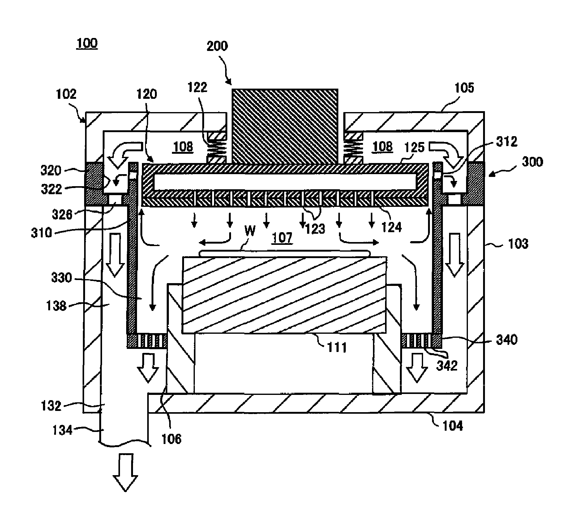
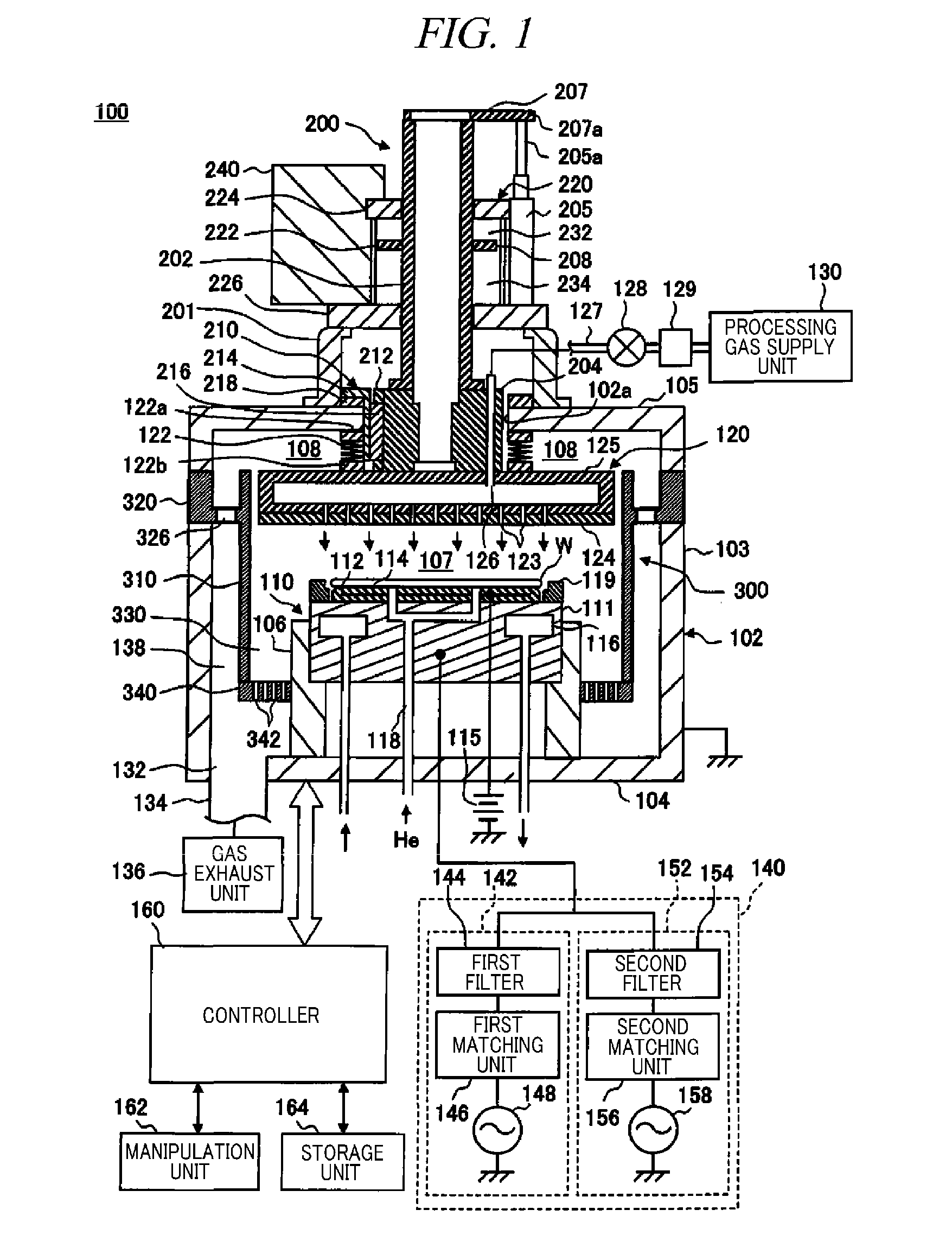
[0027]FIG. 1 shows a schematic configuration of a parallel plate type plasma processing apparatus 100 as an example of a plasma processing apparatus in accordance with an embodiment of the present disclosure. The plasma processing apparatus 100 may include a cylindrical processing chamber 102 made of, e.g., aluminum whose surface is anodically oxidized (alumite treated). The processing chamber 102 is electrically grounded. The processing chamber 102 may have, by way of example, a processing vessel surrounded by a cylindrical sidewall 103, a bottom wall 104 and a ceiling wall 105. The ceiling wall 105 is detachably fixed to an upper portion of the sidewall 103....


PUM

PropertyMeasurementUnit
frequencyaaaaaaaaaa
distanceaaaaaaaaaa
heightaaaaaaaaaa

Abstract

There is provided a plasma processing apparatus capable of easily exhausting a processing gas introduced in a space above a vertically movable upper electrode. The plasma processing apparatus includes a vertically movable upper electrode 120 installed at a ceiling wall 105 of a processing chamber 102 so as to face a lower electrode 111 and having a multiple number of discharge holes 123 for introducing the processing gas; a shield sidewall 310 configured to surround the electrodes and a processing space between the electrodes; an inner gas exhaust path 330 formed at the inside of the shield sidewall and configured to exhaust the atmosphere in the processing space; and an outer gas exhaust path 138 installed at the outside of the shield sidewall and configured to exhaust the processing gas introduced into a space between the upper electrode and the ceiling wall.

Description

CROSS-REFERENCE TO RELATED APPLICATION[0001]This application claims the benefit of Japanese Patent Application No. 2010-119547 filed on May 25, 2010 and U.S. Provisional Application Ser. No. 61 / 354,281 filed on Jun. 14, 2010, the entire disclosures of which are incorporated herein by reference.FIELD OF THE INVENTION[0002]The present disclosure relates to a plasma processing apparatus including an upper electrode capable of vertically moving within a processing chamber.BACKGROUND OF THE INVENTION[0003]As for a plasma processing apparatus for manufacturing a semiconductor device, there is widely used a so-called parallel plate type plasma processing apparatus which includes a lower electrode for mounting thereon a substrate such as a semiconductor wafer, a liquid crystal substrate or the like; and an upper electrode disposed to face the lower electrode in a processing chamber. In this plasma processing apparatus, the substrate is mounted on the lower electrode, a processing gas is int...

Claims


Application Information

Patent Timeline
Patent Type & Authority Patents(United States)
IPC IPC(8): C23C16/509C23F1/00H01L21/306C23C16/455C23C16/06C23C16/22H01J37/32
CPCH01J37/32633H01J37/32477H01J37/32449H01J37/3244H01J37/32568C23C16/45565H01J37/32651H01J37/32834H01L21/02H01L21/0273H01L21/205H01L21/302H01L21/30621H01L21/3065H01L21/31116H01L21/76825H01L21/76826H01L27/105
Inventor HORIGUCHI, MASATOTSUJIMOTO, HIROSHIKITAZAWA, TAKASHI
Owner TOKYO ELECTRON LTD
Why Eureka
Try Eureka