
Optical analyzer for identification of materials using reflectance spectroscopy

an analyzer and reflectance spectroscopy technology, applied in the direction of optical radiation measurement, instruments, spectrometry/spectrophotometry/monochromators, etc., can solve the problems of limiting the use of inspection and quality control applications, high cost, 000) and large size/weight, and achieves reduced power consumption during operation, reduced manufacturing cost, and reduced cost

Active Publication Date: 2014-10-14
INNOVATIVE SCI TOOLS
View PDF55 Cites 5 Cited by
  • Summary
  • Abstract
  • Description
  • Claims
  • Application Information

AI Technical Summary

Benefits of technology

The solution provides accurate identification and quantification of materials with high sensitivity and specificity, offering a cost-effective, portable, and user-friendly alternative to existing technologies, suitable for quality control and forensic analysis.

Problems solved by technology

These desktop instruments have a disadvantage in both high cost (about $50,000) and large size / weight relative to the new system described herein, which would greatly limit their use for inspection and quality control applications where a portable analyzer is needed or advantageous, and in developing countries where the high purchase price is an issue.
These latter spectrometers have a high cost of about $30,000-$45,000.
The tunable acousto-optic spectrometers have also been used for general solid and powdered material identification and also have a high cost greater than $30,000.
To analyze tablets or capsules with this wet chemical test kit it is necessary to dissolve the sample tablet / capsule in water and then add one or more chemical reagents or then to perform a thin layer chromatography step, which are all time consuming and destructive processes (taking over 10 minutes per measurement) which consumes chemical reagents.

Method used


Image

  • Optical analyzer for identification of materials using reflectance spectroscopy
  • Optical analyzer for identification of materials using reflectance spectroscopy
  • Optical analyzer for identification of materials using reflectance spectroscopy

Examples


example specific embodiments

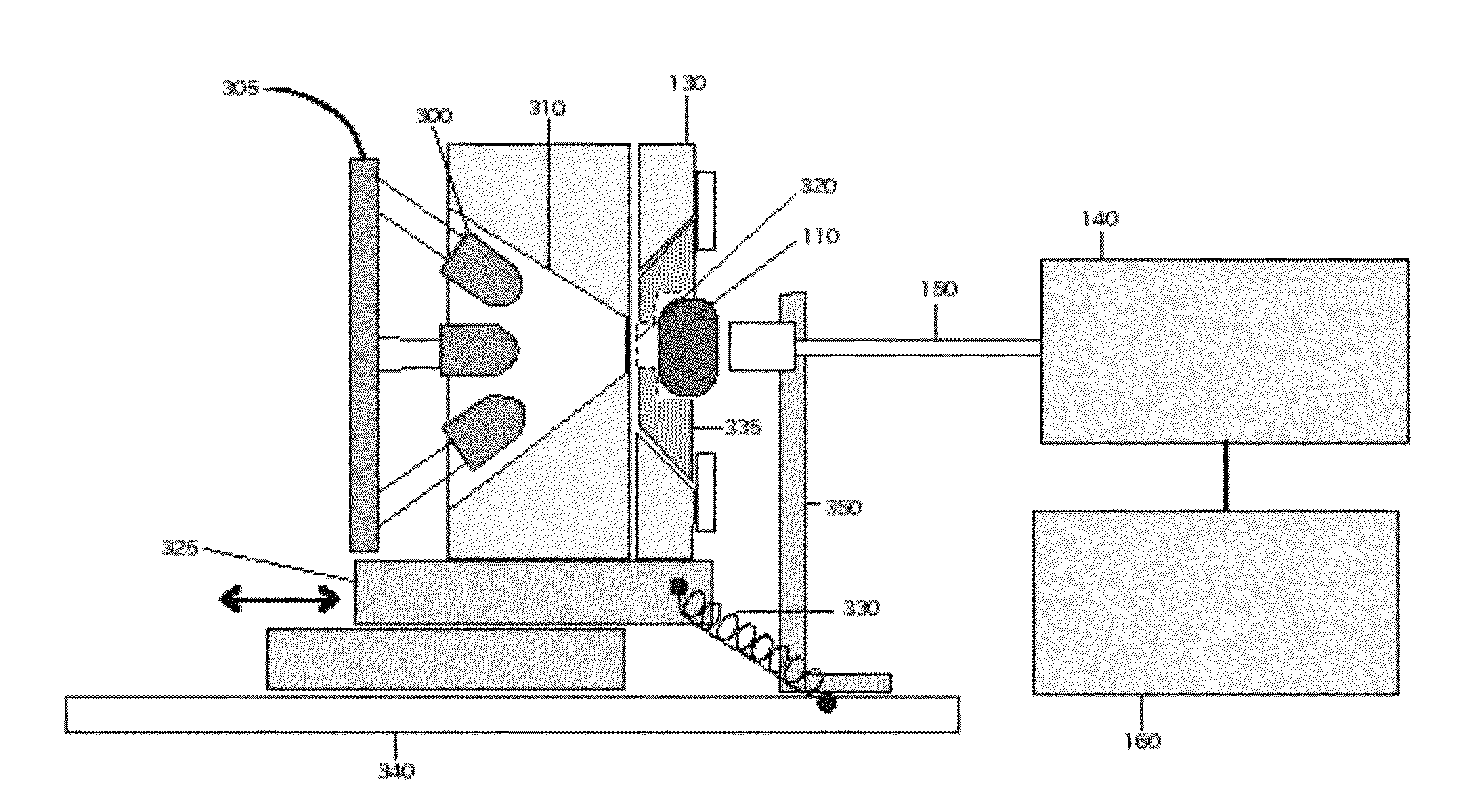
[0071]One specific implementation of a system as shown in FIG. 3 is a multi-LED source NIR spectral analyzer system includes a light source constructed with ten different NIR LEDs arranged in a circular array with two additional LEDs mounted in the center of the array. The multi-LED light source provides continuous light emission over the 700-1050 nm wavelength range. The LEDs have center wavelengths at: 735, 760, 780, 800, 830, 870, 910, 940, 970, and 1020 nm. The ten LEDs at these wavelengths are mounted in a ring shaped array with optical axes mounted at an angle of 45° with respect to the normal to the plane of the LED ring. The 1020 nm LED is the weakest emitter, and the two additional LEDS are 1020 nm LEDs mounted in the center of the circular array with the angle of the optical axis of the two center-mounted LEDs about 7° to the ring normal. FIG. 18 shows LED alignment with the additional LEDs added in the center of the circular array. In this specific implementation, where t...


PUM

PropertyMeasurementUnit
wavelength rangeaaaaaaaaaa
focal lengthaaaaaaaaaa

Abstract

A device and method for identifying solid and powdered materials use near-infrared reflection spectroscopy combined with multivariate calibration methods for analysis of the spectral data. Near-infrared reflection spectroscopy is employed within either the 700-1100 nm or the 900-1700 nm wavelength range to identify solid or powdered materials and determine whether they match specific known materials. Uses include identifying solid and powdered materials with a fast measurement cycle time of about 2 to 15 seconds and with a method that requires no sample preparation, as well as quantitative analysis to determine the concentration of one or more chemical components in a solid or powdered sample that consists of a mixture of components. A primary application involving identification analysis verification of the identify and purity of powdered materials used for fabricating drug tablets and capsules for quality control purposes.

Description

CROSS-REFERENCE TO RELATED APPLICATIONS[0001]This utility patent application claims priority from U.S. provisional patent application Ser. No. 61 / 685,908, filed Mar. 27, 2012, titled “Optical analyzer for identification of materials” in the name of Ronald H. Micheels and Don J. Lee. This utility patent application is also related to co-pending U.S. patent application titled “OPTICAL ANALYZER FOR IDENTIFICATION OF MATERIALS USING TRANSMISSION SPECTROSCOPY” in the name of Ronald H. Micheels and Don J. Lee and filed Mar. 15, 2013.COPYRIGHT NOTICE[0002]A portion of the disclosure of this patent document contains material that is subject to copyright protection. The copyright owner has no objection to the facsimile reproduction by anyone of the patent document or the patent disclosure, as it appears in the Patent and Trademark Office patent file or records, but otherwise reserves all copyright rights whatsoever. Copyright 2013, Innovative Science Tools, Inc.BACKGROUND[0003]1. Field of Te...

Claims


Application Information

Patent Timeline
Patent Type & Authority Patents(United States)
IPC IPC(8): G01J5/02G01N21/25G01N21/35
CPCG01N21/255G01N21/3563G01N21/3577G01N21/359G01N2201/0627G01J3/021G01J3/0218G01J3/18G01N21/8507G01N21/9508G01N2021/475G01N2021/4759G02B6/4298G01N2201/0631G01N2021/0339G01J3/10G01J3/024G01J3/0208G01J3/0216
Inventor MICHEELS, RONALD HLEE, DON J
Owner INNOVATIVE SCI TOOLS
Learn More