Check patentability & draft patents in minutes with Patsnap Eureka AI!

Modulized LED apparatus with enhanced heat dissipation

a technology of leds and heat dissipation, which is applied in the direction of light and heating apparatus, semiconductor devices for light sources, discharge tube main electrodes, etc., can solve the problems of reduced efficiency, color drift in the case of leds, and reduced efficiency of leds operating under high junction temperature, so as to increase the amount of evaporation, transfer the heat generated by the semiconductor device quickly, and increase the effect of efficiency

Inactive Publication Date: 2014-10-14
TAIWAN MASTER HILL TECH CO LTD
View PDF2 Cites 1 Cited by
  • Summary
  • Abstract
  • Description
  • Claims
  • Application Information

AI Technical Summary

Benefits of technology

This solution significantly enhances heat dissipation efficiency with low thermal resistance, allowing semiconductor devices to operate within optimal temperature ranges, improving performance and reducing bulkiness, while maintaining optical functionality.

Problems solved by technology

For example, solar cells, light emitting diodes (LEDs) and thermoelectric semiconductor devices (e.g. thermoelectric generators) operating under high junction temperature will have reduced efficiency, or even color drift in the case of LEDs.
However, to such high power devices, a conventional metal fin heat sink is limited in capability of heat dissipation, and has high thermal resistance, while being bulky and heavy.
However, air bubbles in the boiling liquid are likely to accumulate at the surface of the light converter and thus bar the liquid at the periphery from coming inside to contact the light converter.
Consequently, the heat removal is hindered.
Although the liquid also evaporates at the liquid surface, liquid convection has high thermal resistance, so the efficiency of its thermal transfer is poor, and therefore is weak in heat dissipation.
In addition, the liquid surface of the transparent liquid adversely affects the light converter in terms of absorption for radiant energy and / or light.
Nevertheless, the heat pipe will significantly increase the volume and structural complexity of the solar receiver, being unfavorable to miniaturization of the apparatus.
However, since gas convection has high thermal resistance, the efficiency of its thermal transfer is poor, and therefore is weak in heat dissipation.

Method used


Image

  • Modulized LED apparatus with enhanced heat dissipation
  • Modulized LED apparatus with enhanced heat dissipation
  • Modulized LED apparatus with enhanced heat dissipation

Examples


first embodiment

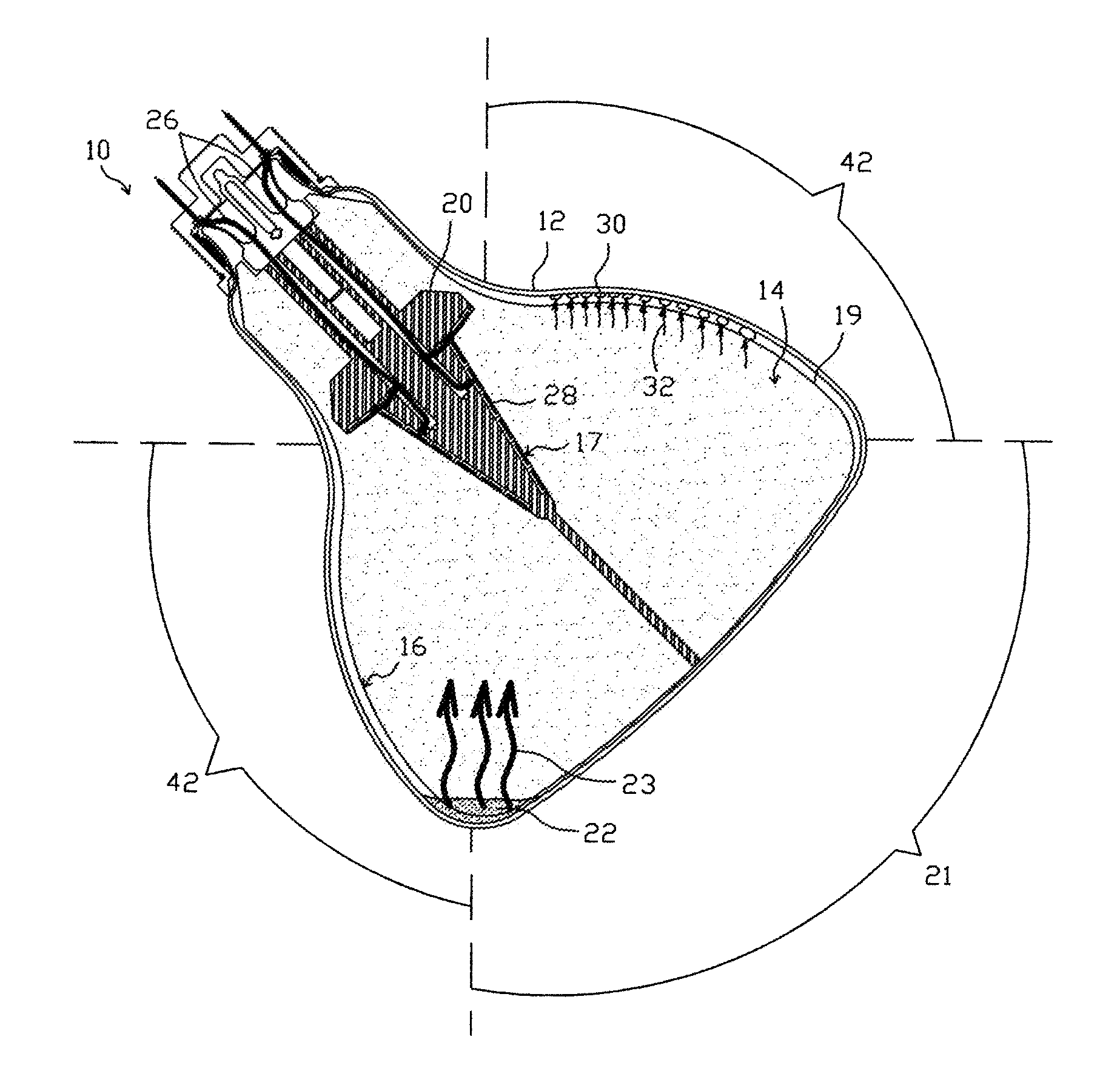
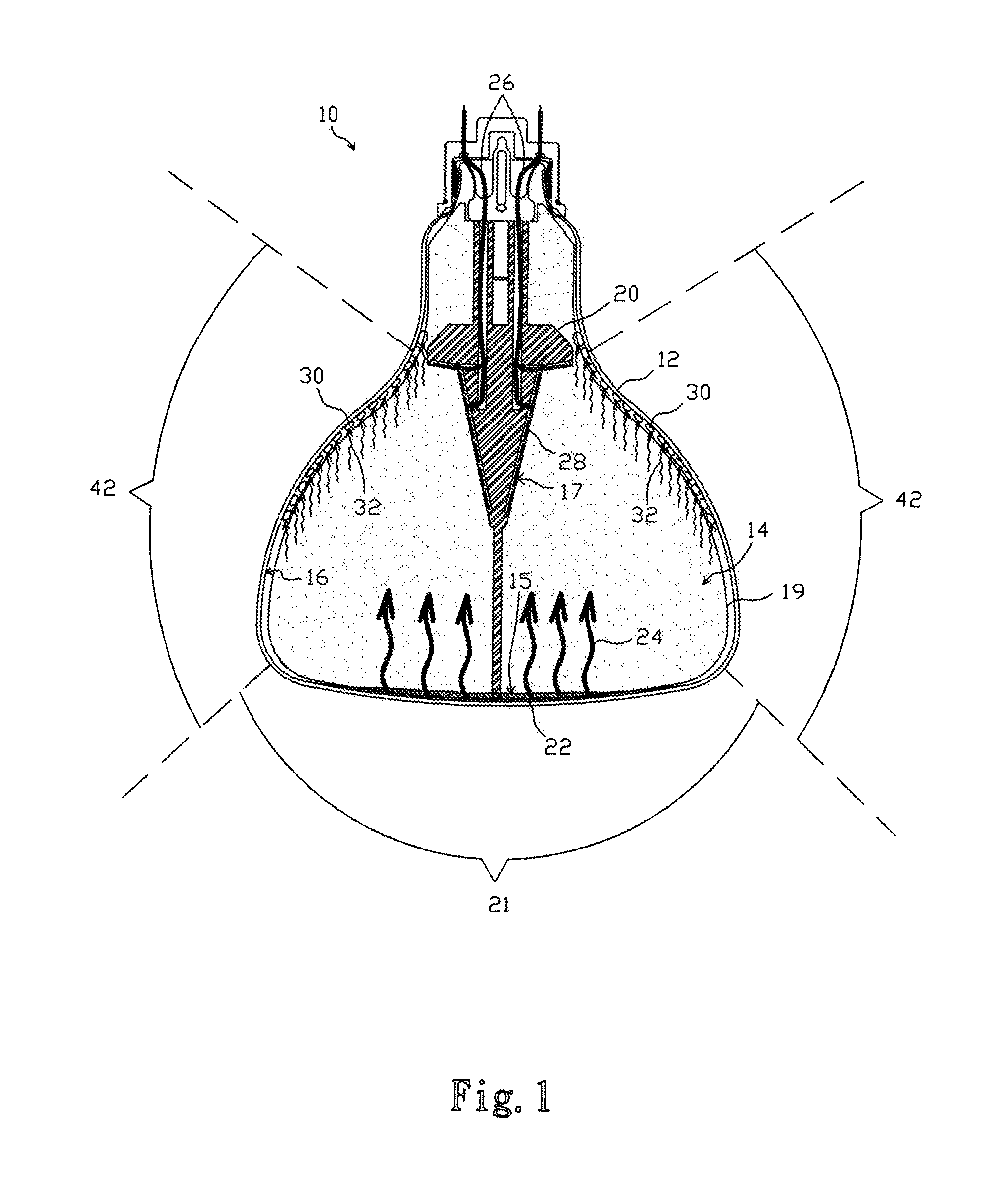
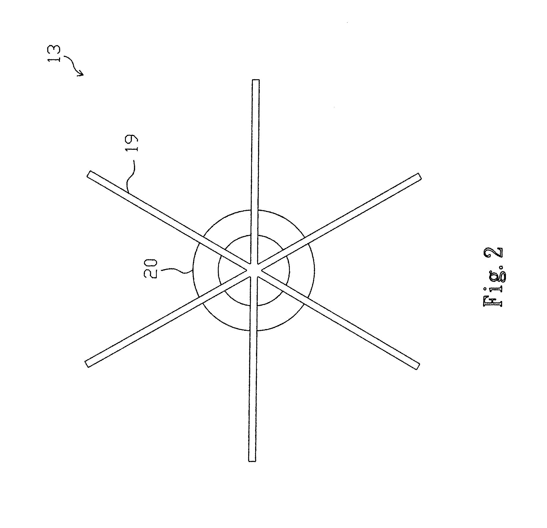
[0040]FIG. 1 shows a first embodiment according to the present invention, in which a heat dissipation enhanced modulized semiconductor apparatus 10 includes a container 12 having an airtight chamber 14 therein, filled with a phase changeable refrigerant such that a liquid refrigerant 22 and a gaseous refrigerant 32 in the chamber 14 will maintain a dynamic balance therebetween. The liquid refrigerant 22 will aggregate at the bottom of the chamber 14 due to gravity, while the gaseous refrigerant 32 pervades the chamber 14. The chamber wall 16 is made of glass, metal or a combination thereof, and has a transparent surface 21 allowing radiant energy and / or light to come into or out from chamber 14. The container 12 has an optical processing area 42 for converging, collecting or diffusing radiant energy and / or light, an evaporator including a heat conductor unit 20 and thermally conductive capillary plates 19 is located in the chamber 14, several semiconductor devices 28 are deposited i...

second embodiment

[0050]FIG. 10 shows a second embodiment according to the present invention, in which a modulized semiconductor apparatus 44 has a bulb-like container 12, and the transparent surface 21 faces downward while being parallel to the horizontal. The modulized semiconductor apparatus 44 includes an evaporation device 45 (referring to FIG. 11) composed of a heat conductor unit 46, thermally conductive capillary plates 50 and a wick 48 and located in the chamber 14. The thermally conductive capillary plates 50 and the wick 48 establish a capillary unit to attract the liquid refrigerant 22 and the ineffective liquid refrigerant 30. As shown in FIG. 11, the heat conductor unit 46 has an opening 52, a plurality of through holes 54 for communicating the opening 52 with the grooves 56. Referring to FIGS. 10 and 11, the wick 48 has one end inserted into the opening 52 and thereby thermally connected to the heat conductor unit 46, and an opposite end falling downward naturally under gravity to cont...

fourth embodiment

[0053]FIG. 15 shows a fourth embodiment according to the present invention. In a modulized semiconductor apparatus 61, an evaporator includes a heat conductor unit 49 and a wick 48, the heat conductor unit 49 has an extension 51, and the wick 48 has one end covering the extension 51 to be thermally connected to the heat conductor unit 49, and an opposite end tailed with a weight 62 so as to keep contacting the liquid refrigerant 22 gathered at the bottom of the chamber 14 and thereby attracting the liquid refrigerant 22 upward under capillarity, as indicated by arrow 55. The extension 51 may include a heat pipe or a vapor chamber made of metal or composite materials.

[0054]The container 12 and evaporator may be designed in shape depending on demands. For example, in the embodiment of FIG. 16, a modulized semiconductor apparatus 64 includes a tubular container 57 having an optical processing area 42, the chamber wall 16 has a transparent surface 21, an evaporator inside the chamber 14...


PUM

PropertyMeasurementUnit
transparentaaaaaaaaaa
thermally conductiveaaaaaaaaaa
areaaaaaaaaaaa

Abstract

A modulized LED apparatus includes a container having a chamber wall with a chamber therein, a transparent surface thereof for the container to be pervious to radiant energy and / or light. The container has an optical processing area for converging, collecting or diffusing radiant energy and / or light. A liquid refrigerant and an evaporator including a heat conductor unit and a capillary unit are in the chamber, and the capillary unit has a portion contacting the liquid refrigerant. With the heat generated by an operating LED device, the evaporator evaporates the liquid refrigerant into a gaseous phase, which then condenses on the chamber wall and thus transfers heat to the chamber wall for dissipating, and the condensed refrigerant is evaporated again by the evaporator again into the gaseous phase. Due to this thermal recycling, the refrigerant continuously transfers heat from the LED device to the ambient environment.

Description

FIELD OF THE INVENTION[0001]The present invention is related to a structure for heat dissipation enhancement for a semiconductor device.BACKGROUND OF THE INVENTION[0002]When a semiconductor device works, it has to stay with a proper range of temperature to maintain good efficiency. For example, solar cells, light emitting diodes (LEDs) and thermoelectric semiconductor devices (e.g. thermoelectric generators) operating under high junction temperature will have reduced efficiency, or even color drift in the case of LEDs. For concentrating solar cells and high power LEDs, heat dissipation is particularly important. However, to such high power devices, a conventional metal fin heat sink is limited in capability of heat dissipation, and has high thermal resistance, while being bulky and heavy.[0003]U.S. Pat. No. 4,211,581 immerses a light converter in a transparent liquid having a low boiling point, such that heat generated by the light converter will heat up the transparent liquid to va...

Claims


Application Information

Patent Timeline
Patent Type & Authority Patents(United States)
IPC IPC(8): H01J7/24F21K99/00F21V3/00F21V3/02F21V3/04F21V7/22F21V29/00F21Y101/02F24S10/40H01L31/00
CPCH01L31/00F21V29/006F21V3/0418F21V3/02F21V3/0472F21K9/135F21V7/22F21V3/005F21Y2101/02H01L2924/0002F21V29/506F21V29/52F21K9/232F21Y2115/10F21V3/061F21V3/10F21V7/28H01L2924/00H01L33/64
Inventor CHANG, LI-FENKUO, WEN-KAI
Owner TAIWAN MASTER HILL TECH CO LTD
Features
  • R&D
  • Intellectual Property
  • Life Sciences
  • Materials
  • Tech Scout
  • Unparalleled Data Quality
  • Higher Quality Content
  • 60% Fewer Hallucinations
Learn More