
Light-emitting arrangement with organic phosphor

a technology of organic phosphor and light-emitting arrangement, which is applied in the direction of discharge tube luminescnet screen, semiconductor device for light source, lighting and heating apparatus, etc., can solve the problems of difficult or costly to prevent any outgasing of wavelength, and achieve the effect of enhancing the lifetime of phosphor

Inactive Publication Date: 2014-10-21
KONINK PHILIPS ELECTRONICS NV +1
View PDF6 Cites 2 Cited by
  • Summary
  • Abstract
  • Description
  • Claims
  • Application Information

AI Technical Summary

Benefits of technology

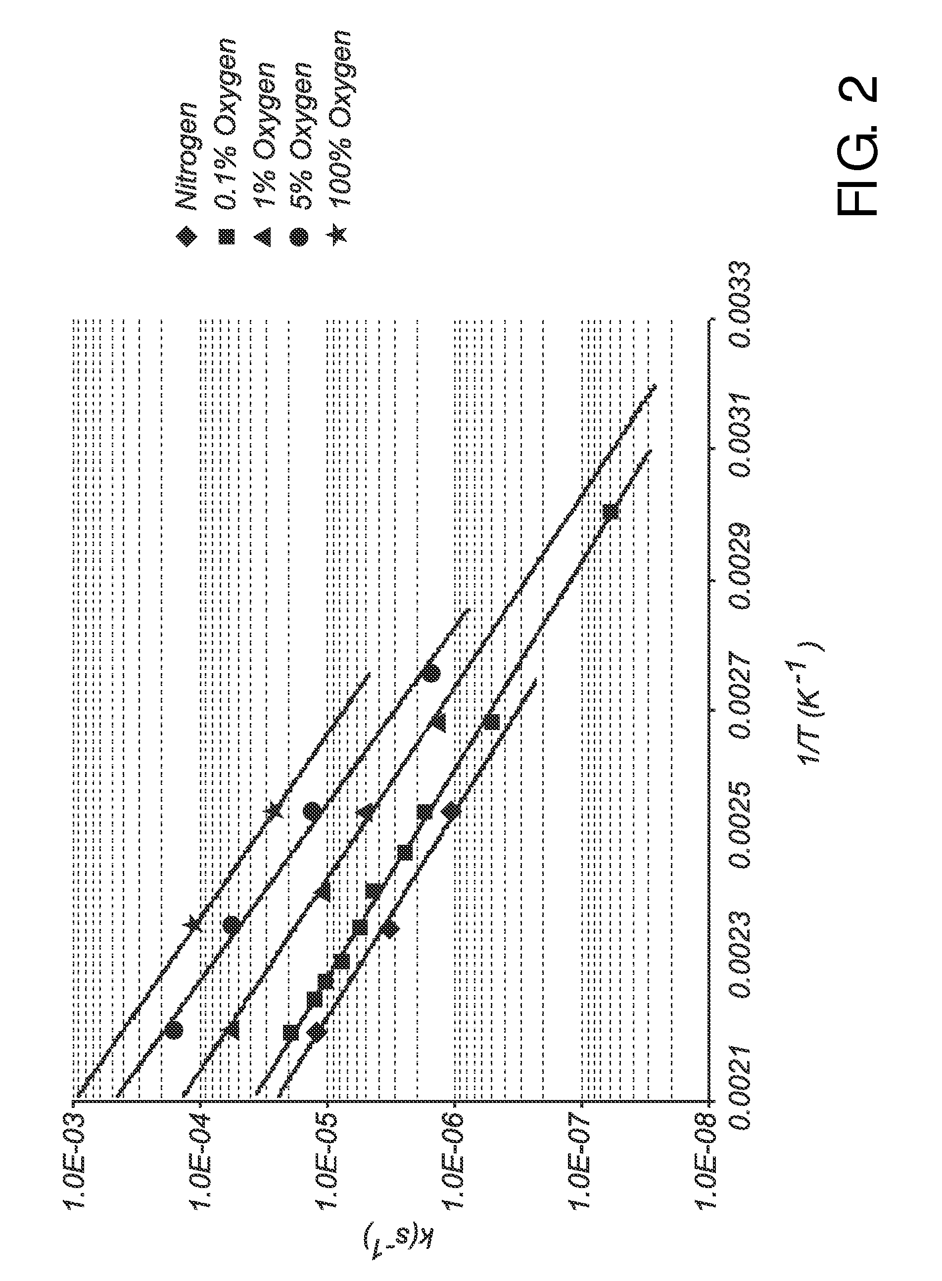
[0010]The inventors have surprisingly found that oxygen concentrations in said range only slightly influence the decay rate of an organic phosphor. These low oxygen contents at ambient or near ambient pressure is easier to achieve and less costly than hermetic sealing of the phosphor under vacuum or a completely inert atmosphere, as have been suggested previously. In addition, it may be difficult or costly to prevent any outgassing of the wavelength converting member or any other components present within the sealing structure during the lifetime of the device. However, the present invention provides the possibility of maintaining the oxygen concentration at an acceptable level. As a result, the lifetime of the organic phosphor increased. The desired oxygen concentration is typically maintained during the entire lifetime of the light-emitting arrangement.
[0022]According to embodiments of the invention, the wavelength converting member comprises a matrix material. The matrix material may be selected from the group consisting of poly(ethylene terephthalate) (PET), PET copolymers, polyethylene naphthalate (PEN) and PEN copolymers. In particular, incorporating the organic phosphor in a PET matrix has been found to greatly enhance the lifetime of the phosphor. However, other suitable matrix materials may also be used.

Problems solved by technology

In addition, it may be difficult or costly to prevent any outgassing of the wavelength converting member or any other components present within the sealing structure during the lifetime of the device.

Method used


Image

  • Light-emitting arrangement with organic phosphor
  • Light-emitting arrangement with organic phosphor
  • Light-emitting arrangement with organic phosphor

Examples


example

[0059]The lifetime of different organic phosphor compounds was tested under different conditions. The compounds used were as follows:

Compound I:

[0060]

Compound II:

[0061]

Compound III:

[0062]

[0063]Compound III is available from BASF as Lumogen® Red F-305 and corresponds to the above general formula in which each of A and C is isopropyl, B is hydrogen and each of D, E, I, L and M is hydrogen.

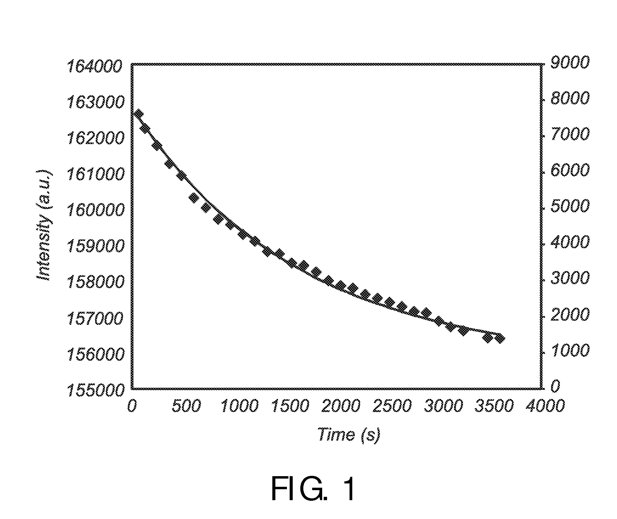
[0064]Each compound was incorporated in two different polymeric matrices, formed into layers, and placed in air or in controlled atmosphere containing 0.1% oxygen. The layers containing the phosphor materials were illuminated with blue light at 4.1 W / cm2 at a temperature of 60° C. The phosphor concentration and the layer thickness were chosen such that the transmission of blue light was 90%. The lifetime of the phosphor was estimated as a 10% reduction in the luminescence intensity. The resulting lifetimes are presented in Table 1.

[0065]

TABLE 1Matrix material; atmosphereCompound ICompound IICompound ...


PUM

PropertyMeasurementUnit
temperatureaaaaaaaaaa
first wavelengthaaaaaaaaaa

Abstract

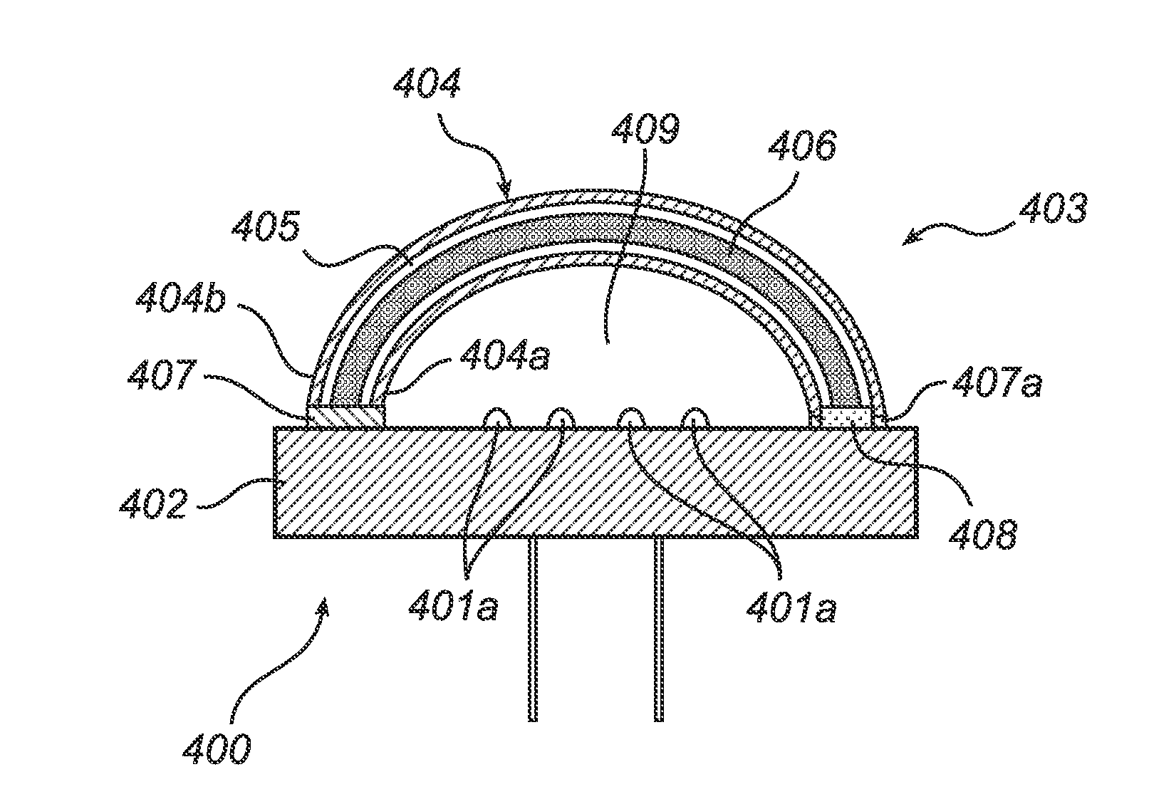
The invention provides a light-emitting arrangement, comprising: a light source adapted to emit light of a first wavelength; a wavelength converting member comprising an organic wavelength converting compound adapted to receive light of said first wavelength and to convert at least part of the received light to light of a second wavelength, said wavelength converting member and said light source being mutually spaced apart; and a sealing structure at least partially surrounding said wavelength converting member to form a sealed cavity containing at least said wavelength converting member, said sealed cavity containing an inert gas and oxygen gas, the concentration of oxygen gas being in the range of from 0.05 to 3% based on the total volume within said sealed cavity. An oxygen concentration in this range has been found to have very limited influence on the life time of the organic wavelength converting compound.

Description

FIELD OF THE INVENTION[0001]The present invention relates to a light-emitting arrangement comprising an organic phosphor maintained under a controlled environment and to a lamp comprising such light-emitting arrangements.BACKGROUND OF THE INVENTION[0002]Light-emitting diode (LED) based illumination devices are increasingly used for a wide variety of lighting applications. LEDs offer advantages over traditional light sources, such as incandescent and fluorescent lamps, including long lifetime, high lumen efficacy, low operating voltage and fast modulation of lumen output.[0003]Efficient high-power LEDs are often based on blue light emitting materials. To produce an LED based illumination device having a desired color (e.g., white) output, a suitable wavelength converting material, commonly known as a phosphor, may be used which converts part of the light emitted by the LED into light of longer wavelengths so as to produce a combination of light having desired spectral characteristics...

Claims


Application Information

Patent Timeline
Patent Type & Authority Patents(United States)
IPC IPC(8): F21V31/03H05B33/04H01L51/00H05B33/14C09K11/06F21Y101/02H01J63/04H01J1/62F21V31/00F21K99/00
CPCH05B33/04F21K9/56F21Y2101/02H05B33/14H01L51/0053H01L2251/5361C09K2211/1044F21V31/005C09K11/06F21V31/03F21K9/64F21Y2115/10H10K85/621
Inventor HIKMET, RIFAT ATA MUSTAFACILLESSEN, JOHANNES FRANCISCUS MARIAWEGH, RENE THEODORUS
Owner KONINK PHILIPS ELECTRONICS NV
Learn More