Cooling device for pluggable module, assembly of the cooling device and the pluggable module

a technology of cooling device and pluggable module, which is applied in the direction of lighting and heating apparatus, electrical apparatus casing/cabinet/drawer, instruments, etc., can solve the problems of heat conduction, not well contact between pluggable components and frames, and solution only fits for sfp transceiver modules with small power consumption

Inactive Publication Date: 2014-11-04
TELEFON AB LM ERICSSON (PUBL)
View PDF27 Cites 31 Cited by
  • Summary
  • Abstract
  • Description
  • Claims
  • Application Information

AI Technical Summary

Benefits of technology

[0010]An object of the present invention is to provide a compact cooling device for cooling at least one pluggable module efficiently.
[0015]According to one aspect of the invention, a bracket is arranged between the thermal conductive block and the heat radiator to fix the thermal conductive block to the heat radiator through the resilient thermal conductive pad. The bracket comprises an aperture defined therein for holding the thermal conductive block and the resilient thermal conductive pad and two flanges at both sides thereof for fixing with the heat radiator. The bracket is preferably substantially U-shaped with a concave on the side of the aperture. The flanges of the bracket are fixed to the heat radiator by screws or rivets. The arrangement of the bracket has an advantage of fixing the thermal conductive block and the heat radiator integrally and compactly, thus further enhancing the heat dissipation property therebetween.

Problems solved by technology

However, the pluggable component and frame are not well contacted.
There is inevitably an air gap between the pluggable component and an inside surface of the frame, which blocks the heat conduction therebetween.
Since there is a big thermal resistance for heat dissipation from frame to air, this solution only fits for an SFP transceiver module with small power consumption.
With the data transfer rate growing, the power consumption of the pluggable module is increasing.
Since the size of the heat sink is usually limited, under the condition of multiple pluggable modules assembling in one system, it usually requires an additional forced convection unit to enhance the heat dissipation efficiency, thus making the system relatively complex.

Method used


Image

  • Cooling device for pluggable module, assembly of the cooling device and the pluggable module
  • Cooling device for pluggable module, assembly of the cooling device and the pluggable module
  • Cooling device for pluggable module, assembly of the cooling device and the pluggable module

Examples


Embodiment Construction

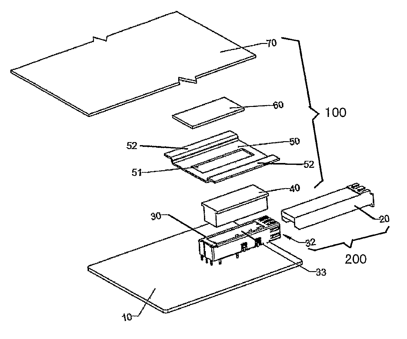
[0030]FIG. 1 is a schematic exploded perspective view of an assembly of a cooling device 100 and a pluggable module 200 adapted to be mounted on a PCB 10 of an embodiment according to the present invention. The cooling device 100 includes a thermal conductive block 40, a bracket 50, a resilient thermal conductive pad 60 and a heat radiator 70. The pluggable module 200 includes a pluggable electronics 20 and a frame 32 for accommodating such a pluggable electronics 20.

[0031]The pluggable module 200 shown in FIG. 1 is an SFP optical transceiver module, but the pluggable module 200 can be any type of power consumption electronic module with a pluggable component. The metal frame 32 and a connector (not shown) are mounted on a circuit board 10. The metal frame 32 has a side opening (not labeled) to allow the pluggable component 20 to plug in. The connector is used to realize the connection between the pluggable module 200 and circuit board 10 mechanically and electrically. The frame 32 ...


PUM


Abstract

Provides a cooling device (100) for cooling at least one pluggable module (200) each having a pluggable component (20) and a frame (32) for accommodating the pluggable component, the frame having an opening (33) on a top wall thereof. The cooling device comprises at least one thermal conductive block (40), a heat radiator (70) and a resilient thermal conductive pad (60). The resilient thermal conductive pad being adapted to be in a substantially released position when the pluggable component is decoupled from the frame and substantially biased when the pluggable component is inserted into the frame thus exerting a biasing force on the thermal conductive block and the heat radiator whereby the thermal conductive block is pressed through the opening of the frame into direct thermal contact with the pluggable element of the pluggable module for conducting the heat generated by the pluggable component to the heat radiator through the thermal conductive block and the resilient thermal conductive pad. The main advantage of the cooling device is that the pluggable module has a reinforced and compact cooling structure that improves the heat dissipation efficiency.

Description

BACKGROUND OF THE INVENTION[0001]1. Field of the Invention[0002]The present invention relates generally to a cooling device for cooling a pluggable module, and more particularly to a cooling device for a small form-factor pluggable (SFP) optical transceiver module.[0003]2. Description of the Prior Art[0004]Transceivers are utilized to interconnect circuit cards of communication links and other electronic modules or assemblies. Various international and industry standards define the type of connectors used to connect computers to external communication devices, such as modems, network connectors, and other transceivers. A well-known type of transceiver module known as Gigabit Connector Converter (GBIC) provides a connection between a computer and an Ethernet, Fiber Channel, or another data communication environment.[0005]It is desirable to miniaturize transceivers in order to increase the port density at a network connection (at switch boxes, cabling patch panels, wiring closets, com...

Claims


Application Information

Patent Timeline
Patent Type & Authority Patents(United States)
IPC IPC(8): F28F9/007F28F21/00G01F1/20H05K7/20G02B6/42
CPCG02B6/428G02B6/4246G02B6/4261G02B6/4269
Inventor SHI, KRIS
Owner TELEFON AB LM ERICSSON (PUBL)
Why Eureka
Try Eureka