Method for producing battery electrode

a battery electrode and electrode body technology, applied in the direction of cell components, final product manufacturing, sustainable manufacturing/processing, etc., can solve the problems of increasing friction resistance with solvents, reducing battery performance, and polymer fibers showing larger surface irregularities, so as to reduce the adhesion between the active material layer 7 and the collector 5 , the effect of reducing the drop in battery performan

Active Publication Date: 2014-12-02
TOYOTA JIDOSHA KK
View PDF19 Cites 4 Cited by
  • Summary
  • Abstract
  • Description
  • Claims
  • Application Information

AI Technical Summary

Benefits of technology

[0011]However, convection occurs during drying of a paste coat material when an active material layer forming paste that contains a negative electrode active material 1, a binder 2 and a thickener 3, is coated onto a collector 5 and is dried rapidly, to produce the abovementioned negative electrode, as illustrated in FIG. 8; also, a migration phenomenon occurs whereby the thickener 3 in the vicinity of the collector 5 rises up to a surface layer section of the paste coat material 4 together with the binder 2. As a result of this migration phenomenon, the amount of binder 2 and thickener 3 in the vicinity of the collector 5 decreases, and adhesion between the active material layer 7 and the collector 5 is reduced. This lowered adhesion may cause a drop in battery performance (cycle durability and the like). It is a main object of the present invention, arrived at in the light of the above issues, to provide a method for producing a battery electrode that exhibits good adhesion between a collector and an active material layer through suppression of the above-described migration phenomenon.
[0013]A fibrillation process in the present invention denotes a process of finely splitting polymer fibers and that can be accomplished, for instance, by resorting to mechanical shear forces. The surface of the fibrillated polymer fibers unravels, whereupon numerous fine fibers (fibrils) become formed on the fibers. As a result, the polymer fibers exhibit larger surface irregularities, increased frictional resistance with a solvent, and lower mobility in the solvent (ease of motion of the polymer fibers in the solvent) than polymer fibers that have not been fibrillated.
[0014]In the production method of the present invention, polymer fibers the mobility whereof is lowered as a result of the above-described fibrillation process are used as at least one type of the polymer materials (for instance, binder and thickener). Therefore, the polymer materials in the vicinity of the collector do not rise readily to the surface layer section of the paste coat material, even if convection occurs during drying of the paste coat material. As a result, it becomes possible to secure an amount of polymer materials in the vicinity of the collector, and to increase the adhesion between the active material layer and the collector. By virtue of the above features, thus, segregation of the polymer materials, which is caused by the migration phenomenon, can be eliminated or mitigated, and it becomes possible to produce an electrode that comprises an active material layer having good adhesion towards the collector.
[0015]In a preferred configuration of the production method disclosed herein, the polymer materials contain a first polymer that functions as a binder and a second polymer that functions as a thickener of the paste, in the active material layer, and the fibrillated polymer fibers are used as at least the second polymer. In such a case, the mobility of the thickener (second polymer) decreases as a result of the fibrillation process, and hence it becomes possible to suppress the phenomenon whereby the thickener in the vicinity of the collector rises up to the surface layer section of the paste coat material, accompanying the binder (first polymer), even if convection occurs during drying of the paste coat material. As a result, the amount of binder and thickener in the vicinity of the collector can be secured, and adhesion between the active material layer and the collector can be enhanced.
[0017]In a preferred configuration of the production method disclosed herein, cellulosic fibers (for instance, carboxymethyl cellulose) are used as the fibrillated polymer fibers. Cellulosic fibers are preferably used as the thickener of the abovementioned paste, in terms of facilitating the fibrillation process.
[0019]The present invention provides a battery (for instance, a lithium secondary battery) that is constructed using an electrode produced in accordance with any one of the production methods disclosed herein. The battery exhibits superior battery performance by virtue of being constructed using, as at least one of the electrodes, an electrode (for instance, the negative electrode) that boasts good adhesion between a collector and an active material layer, as described above. For instance, a battery that satisfies at least one property from among superior output characteristic, high cycle durability and good production efficiency, can be provided by constructing the battery using the abovementioned electrode.

Problems solved by technology

This lowered adhesion may cause a drop in battery performance (cycle durability and the like).
As a result, the polymer fibers exhibit larger surface irregularities, increased frictional resistance with a solvent, and lower mobility in the solvent (ease of motion of the polymer fibers in the solvent) than polymer fibers that have not been fibrillated.
Therefore, the polymer materials in the vicinity of the collector do not rise readily to the surface layer section of the paste coat material, even if convection occurs during drying of the paste coat material.

Method used


Image

  • Method for producing battery electrode
  • Method for producing battery electrode
  • Method for producing battery electrode

Examples


Embodiment Construction

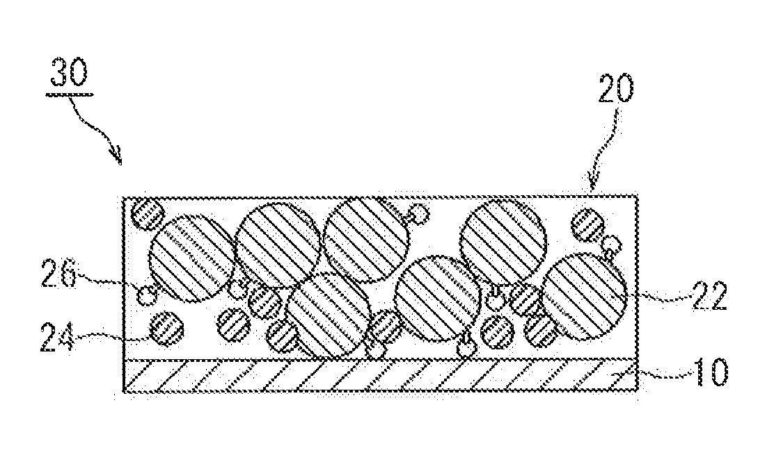
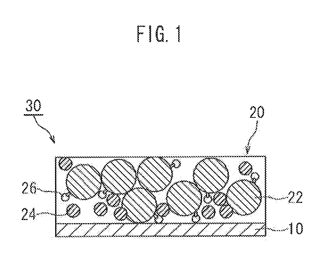
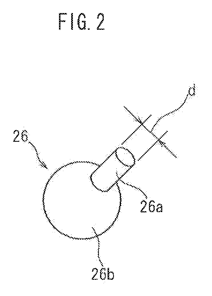
[0029]Embodiments of the present invention are explained below with reference to accompanying drawings. In the drawings below, members and sites that elicit identical effects are denoted with identical reference numerals. The dimensional relationships (length, width, thickness and so forth) in the drawings do not reflect actual dimensional relationships. Any features other than the features specifically set forth in the present description and which may be necessary for carrying out the present invention (for instance, the configuration and production method of electrode bodies that comprise a positive electrode and a negative electrode, the configuration and production method of a separator and an electrolyte, as well as ordinary techniques relating to the construction of the battery of the present invention and other batteries) can be regarded as instances of design matter that a person skilled in the art can address on the basis of known techniques in the technical field in quest...


PUM

PropertyMeasurementUnit
pressureaaaaaaaaaa
diameteraaaaaaaaaa
diameteraaaaaaaaaa

Abstract

A main object of the present invention is to provide a method for producing a battery electrode that has excellent adhesion between a collector and an active material layer by suppressing a migration phenomenon. The method for producing a battery electrode of the present invention is a method for producing a battery electrode 30 that has a structure in which an active material layer 20 that includes an active material 22 is held on a collector 10. The method includes a step of applying, onto the collector 10, an active material layer forming paste that contains the active material 22 and polymer materials 24, 26 in a solvent; and a step of drying the applied paste coat material, to form thereby the active material layer 20 on the collector 10. Fibrillated polymer fibers 26 are used as at least one of the polymer materials 24, 26.

Description

CROSS-REFERENCE TO RELATED APPLICATIONS[0001]this application is a national phase application of International Application No. PCT / JP2010 / 064418, filed Aug. 25, 2010, the content of which is incorporated herein By reference.TECHNICAL FIELD[0002]The present invention relates to a method for producing a battery electrode, and more particularly to a method for producing a battery electrode that has a configuration in which an electrode mix layer containing an electrode active material is held on a collector.BACKGROUND ART[0003]Recent years have witnessed the growing importance of secondary batteries, such as lithium ion batteries and nickel-hydride batteries, as vehicle-mounted power sources, and as power sources that are provided in, for instance, personal computers and portable terminals. In particular, lithium secondary batteries that are lightweight and afford high energy density are expected to come to be used as preferred high-output power sources that are installed in vehicles. ...

Claims


Application Information

Patent Timeline
Patent Type & Authority Patents(United States)
IPC IPC(8): H01M4/13H01M4/133H01M4/62H01M4/139H01M4/1393H01M10/0525H01M4/04
CPCH01M10/0525H01M4/0404H01M4/62H01M4/133H01M4/622H01M4/1393H01M4/139H01M4/623Y02E60/122H01M4/13Y02T10/7011Y02E60/10H01M10/05Y02P70/50Y02T10/70
Inventor TAMAKI, TAKUMIHASHIMOTO, TATSUYA
Owner TOYOTA JIDOSHA KK
Why Eureka
Try Eureka