Device and method for indicating if a fastening element has reached a tensile yield limit load

a technology of tensile yield and fastening element, which is applied in the direction of force sensors, instruments, force/torque/work measurement apparatus, etc., can solve the problems of increasing the weight of the structure comprising the fastening element and the piece, the fastening element can be weakened or broken, and the structure can be weighed down. , to achieve the effect of optimizing the fastening of the fastening element, and reducing the weight of the structur

Active Publication Date: 2014-12-16
CARBON COMPENSATE SCANDINAVIA AB (ID 556784 0847)
View PDF10 Cites 9 Cited by
  • Summary
  • Abstract
  • Description
  • Claims
  • Application Information

AI Technical Summary

Benefits of technology

[0014]The device has the advantage that no physical contact with the fastening element is necessary for indicating the tensile yield limit load. Thereby, the tensile yield limit load can be indicated during fastening of the fastening element in the piece. By means of the device, it is possible to avoid that the fastening element is being fastened to a load that results in a weakening or break of the fastening element. Moreover, the risk that the fastening element is fastened to a too low stress for holding together the structure is reduced.
[0015]Based on the information on tensile yield limit load it is possible to optimize the fastening of the fastening element in the piece. Thereby, it is possible to reduce the weight of a structure comprising the fastening element and the piece. The device can be used on all types of fastening elements with a shaft that comprises a magnetostrictive material.
[0030]According to an embodiment of the invention, the device comprises means for generating a static magnetic field that penetrates the shaft. By means of the static magnetic field the significant change of the physical quantity is enhanced, wherein the detection of the significant change of the physical quantity is facilitated.
[0032]According to an embodiment of the invention, the control unit is adapted to interrupt the torsion transfer unit transferring of the torsion force to the fastening element at an indication of a reached tensile yield limit load. Thereby, the fastening element is prevented from being loaded into the plastic state.
[0061]The determination of the significant change using the offset strain provides an improved reliability in determining and indicating that the fastening element has reached the tensile yield limit load in comparison to a deviation from a the mainly constant rate of change of the physical quantity.

Problems solved by technology

If the fastening element is loaded to a too high stress the fastening element can be weakened or break.
Accordingly, the fastening element is not used optimally, which results in that thicker dimensions or greater number of fastening elements is necessary.
The thicker dimension of the fastening element or the greater number of fastening elements subsequent results in that the weight of a structure comprising the fastening element and the piece increases.
For example when fastening element is used in transport structures, such as cars, trains, aeroplanes, etcetera, an increased weight of the structure results in increased operation costs.
The method has the disadvantage that the transmitter and the torsion head of the fastening element must be in physical contact with each other and that contact means, such as a gel or similar is necessary in order to obtain sufficient signal transferring.
Thereby it is difficult to perform the measurement of the stress in the fastening element at a rotating state of the fastening element.
The method is on the other hand not applicable to a multi axis stress condition for determining a tensile yield limit load, such as at fastening of a fastening element comprising tensile and torsion stresses, because the maximum of the magnetic susceptibility does not correspond to the multi axis tensile yield limit load.

Method used


Image

  • Device and method for indicating if a fastening element has reached a tensile yield limit load
  • Device and method for indicating if a fastening element has reached a tensile yield limit load
  • Device and method for indicating if a fastening element has reached a tensile yield limit load

Examples


Embodiment Construction

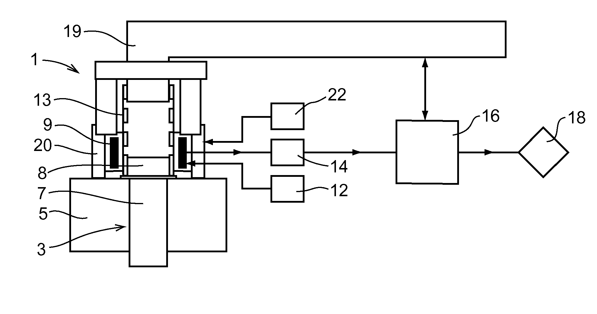
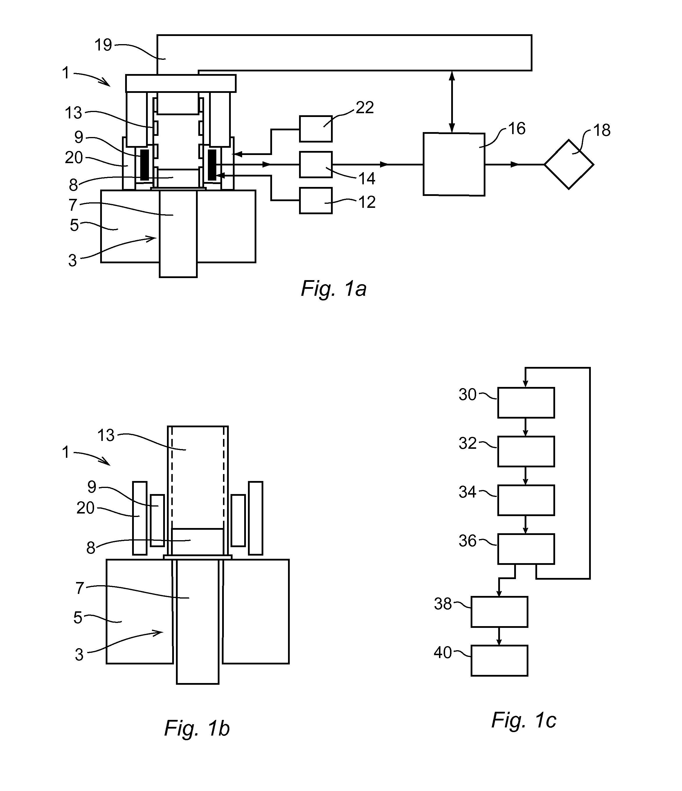
[0088]FIG. 1a discloses a cross section of a device 1 for determining and indicating if a fastening element 3 at fastening in a piece 5 has reached a tensile yield limit load. FIG. 1b discloses an enlargement of a part of the device 1 that is shown in FIG. 1a. The determination and the indication of the tensile yield limit occurs accordingly in real time during fastening of the fastening element 3.

[0089]The fastening element 3 comprises a threaded shaft 7 that comprises a magnetostrictive material. The fastening element 3 can for example be a screw or similar threaded element. The threaded shaft 7 comprises a magnostrictive material, which material's magnetic properties are influenced by mechanical stress in the material. The magnetostrictive material comprises for example different alloys of iron or nickel. The fastening element 3 has a torsion head 8 in connection to the threaded shaft 7 for receiving a torsion force.

[0090]The device 1 comprises means 9, 12 for generating an alter...


PUM

PropertyMeasurementUnit
frequencyaaaaaaaaaa
frequencyaaaaaaaaaa
frequencyaaaaaaaaaa

Abstract

A device and method for indicating if a fastening element upon fastening to a piece has reached a tensile yield limit load. The fastening element includes a threaded shaft having a magnetostrictive material. The device includes a mechanism for generating an alternating magnetic field that penetrates the shaft, a mechanism for measuring a physical quantity that depends on the momentary magnetic susceptibility of the shaft and a control unit adapted to detect a significant change of the physical quantity and determine and indicate if the shaft of the fastening element has reached the tensile yield limit load.

Description

CROSS-REFERENCE TO RELATED APPLICATION[0001]This application is the U.S. national phase of PCT Appln. No. PCT / EP2011 / 059491 filed on Jun. 8, 2011, which claims priority to Swedish Patent Application No. 1050589-9 filed on Jun. 8, 2010, the disclosures of which are incorporated in their entirety by reference herein.TECHNICAL FIELD OF THE INVENTION[0002]The present invention relates to a device and a method for indicating if a fastening element at fastening in a piece has reached a tensile yield limit load. The fastening element comprises a threaded shaft, which shaft comprises a magnetostrictive material.PRIOR ART[0003]At fastening of the fastening element in the piece influence of friction between the fastening element and the piece results in that the stress in the fastening element only roughly can be estimated. If the fastening element is loaded to a too high stress the fastening element can be weakened or break. Due to the uncertainty in the stress of the fastening element, it i...

Claims


Application Information

Patent Timeline
Patent Type & Authority Patents(United States)
IPC IPC(8): G01L3/10G01L5/24G01B7/16G01L5/00
CPCG01L5/0042G01L3/102G01L5/24B25B23/14G01L1/12G01L3/10G01L5/00G01N27/72B25B23/1425
Inventor CARLSSON, ROLFJOHANSSON, CHRISTERAHRENTORP, FREDRIKJONASSON, CHRISTIANBLOMGREN, JAKOB
Owner CARBON COMPENSATE SCANDINAVIA AB (ID 556784 0847)
Why Eureka
Try Eureka