Microvalve and sealing device for use in a microfluidics system, and method for the production thereof

a microfluidics and sealing device technology, applied in the direction of plug valves, lift valves, nuclear energy welding apparatus, etc., can solve the problems of onetime assembly still too elaborate in practice for mass production, difficult valve manipulation, etc., to achieve easy miniaturization, high integration density, and high density

Active Publication Date: 2014-12-16
FRAUNHOFER GESELLSCHAFT ZUR FOERDERUNG DER ANGEWANDTEN FORSCHUNG EV
View PDF13 Cites 6 Cited by
  • Summary
  • Abstract
  • Description
  • Claims
  • Application Information

AI Technical Summary

Benefits of technology

[0010]The problem of the present invention, accordingly, is to improve a microvalve as well as a sealing device of the aforementioned kind so that it can be produced with low effort and thus with low costs. Accordingly, the problem of the invention is to provide a method for the production of such a microvalve or a corresponding cover device that is more economical and thus suited for the mass production of disposable products.
[0022]The shape-stable part ensures a uniform distribution of the pressing force over the entire sealing surface of the elastomer seal, while the latter due to its elasticity is compressed and provides a sufficient sealing.
[0024]In this way, the shape-stable part, which in this embodiment preferably consists of a shape-stable plastic, and the elastomer seal are combined into a single valve body, which reduces the assembly expense. Also, the production of a two-component injection-molded part is relatively economical.
[0026]This embodiment of the invention has the advantage of easy workmanship. Channels in the form of depressions or grooves, if the valve body is not finished by injection molding, are produced or added subsequently in familiar fashion by etching, laser ablation, spray engraving, hot engraving, milling or the like. On the other hand, the channel in the form of a through opening can be produced in a single stamping process and a valve body with such an elastomer seal is therefore more favorable.
[0029]The microvalve or the sealing device on account of their makeup are easy to miniaturize. The functional components of valve and / or sealing device can therefore be arranged with higher density on the microfluidic chip. It is also possible to use both sides of a chip for mounting. In this way, even higher integration densities and more complex channel structures and thus an improved functionality can be achieved for the same footprint on a chip.
[0030]The microvalve or sealing device of the invention, especially when combined with a recessed seat, can be integrated almost fully in the sample processing chip when the valve seat or the seat for the sealing element is worked so deep in the form of a recess into the sample processing chip that the valve body can be set fully in the processing chip. Moreover, the clamping element can also be integrated in the sample processing chip, at least partly, by suitable depressions or recesses in it. In this way, the integration density of the functional components is further increased and the chip is given a flat profile, even when the functional components of valve and / or sealing device are mounted on both sides.

Problems solved by technology

Even though the rotor and the stator are loose parts in this case and seem suitable for onetime use, still a considerable expense is required to assembly the functional valve and thus the manipulation of the valve become more difficult.
The microvalve arrangement of FIG. 1 is of simple construction when compared to the aforesaid prior art, yet still a multitude of different materials and components are needed and the onetime assembly is still too elaborate in practice for a mass production.

Method used


Image

  • Microvalve and sealing device for use in a microfluidics system, and method for the production thereof
  • Microvalve and sealing device for use in a microfluidics system, and method for the production thereof
  • Microvalve and sealing device for use in a microfluidics system, and method for the production thereof

Examples


Embodiment Construction

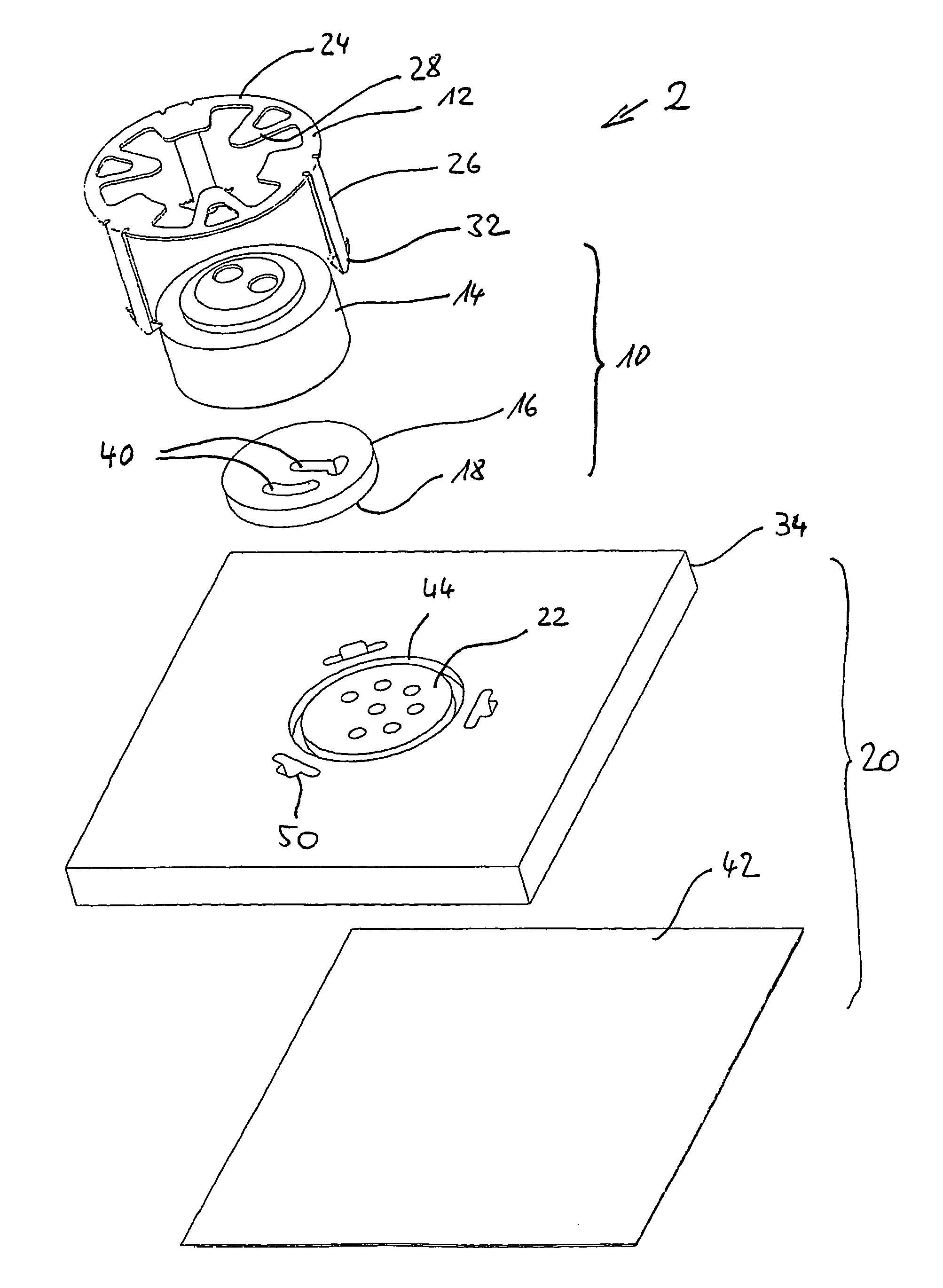
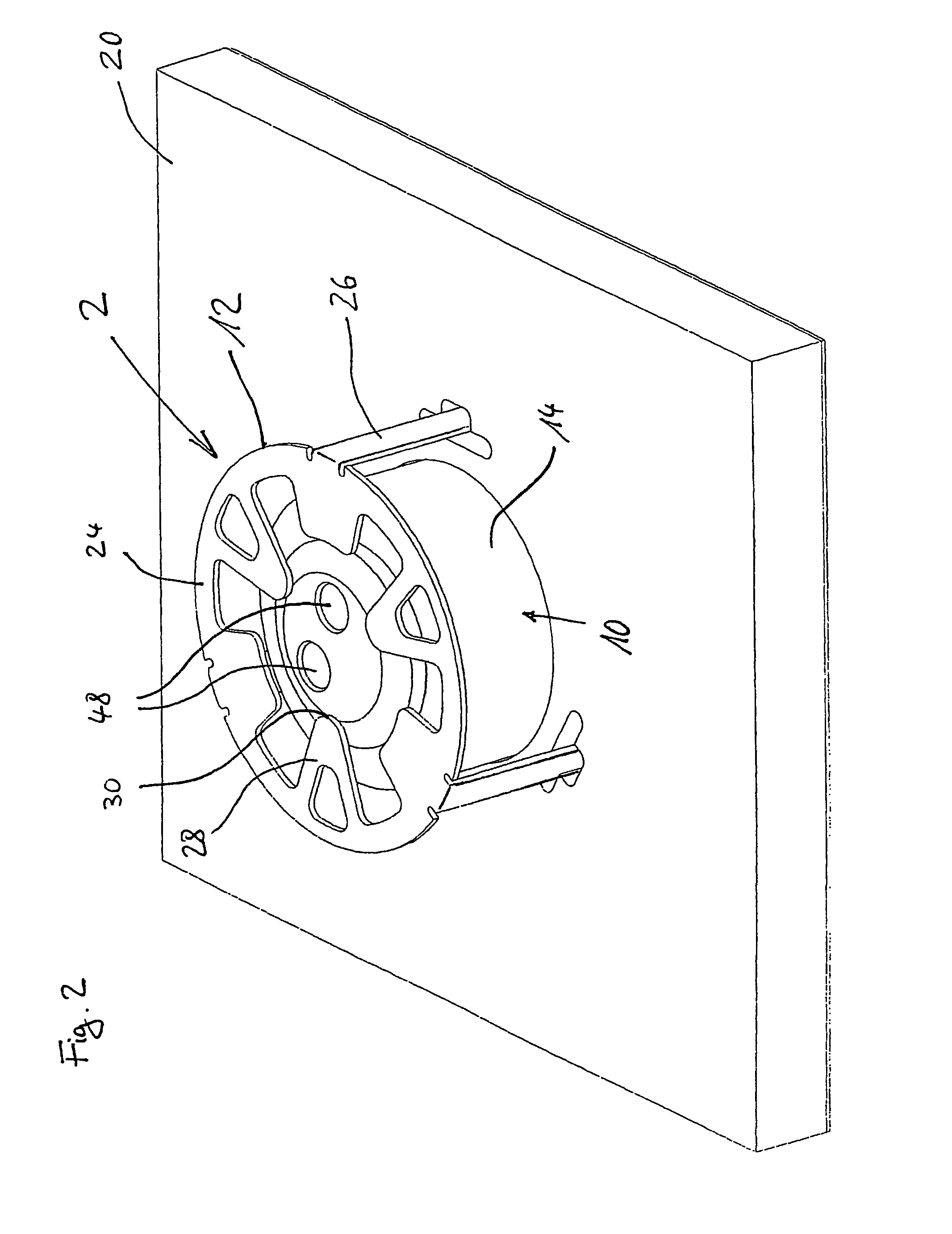
[0038]A first embodiment of the microvalve of the invention with sample processing chip is shown in perspective view from various directions and partly sectioned in FIGS. 2 to 5, to which we shall refer in what follows.

[0039]The microvalve is designed as a rotary valve 2 and has an essentially cylindrical valve body 10 and a clamping element 12 that supports it. The valve body 10 consists of a shape-stable part 14 and an elastomer seal 16, on whose bottom side a sealing surface 18 is formed. The valve 2 is arranged in the manner described hereafter on a substrate in the form of a sample processing chip 20 and secured. By its sealing surface 18, the valve lies on a corresponding sealing surface 22 of the substrate 20.

[0040]The clamping element 12 in this embodiment is stamped out from a plate of spring steel and bent into the three-dimensional shape depicted. The clamping element 12 has an annular segment 24 for pressing on the valve body 10 and three downward bent anchor elements 26...


PUM

PropertyMeasurementUnit
flexural-elasticaaaaaaaaaa
compressive-elasticaaaaaaaaaa
elasticaaaaaaaaaa

Abstract

A microvalve for controlling fluid flows, and a sealing device for sealing cavities in a microfluidic system, particularly in a lab-on-a-chip system, and a method for the production thereof. A sealing surface of a valve body, or a sealing element, respectively, rests on a sealing surface of a substrate and is pressed against the sealing surface of the substrate in a fluid-tight manner by means of a clamping element. The clamping element and / or the valve body, or the sealing element, respectively, are at least partially elastic.

Description

FIELD OF INVENTION[0001]The invention concerns a microvalve for control of fluid streams and a sealing device for the sealing of cavities in a microfluidics system, especially in a lab-on-a-chip system as well as a method for its production. The microvalve has a substrate with a sealing surface and a valve body disposed movably relative to the substrate, which has a sealing surface and defines at least one channel for optional connection and / or separation of fluid lines in the substrate, wherein the sealing surface of the valve body and the sealing surface of the substrate lie against each other in a fluid-tight manner. The sealing device has a substrate with a sealing surface and a sealing element, having a sealing surface for sealing off a cavity in the substrate. The invention further relates to a sample processing chip with such a microvalve and / or such a sealing device.[0002]A sample processing chip in the sense of this invention is a microfluidic system for chemical and bioche...

Claims


Application Information

Patent Timeline
Patent Type & Authority Patents(United States)
IPC IPC(8): F16K99/00B01L3/00B01L99/00F01L7/06B23P11/00F16J15/02
CPCF16K2099/0084F16K99/0001B01L3/502738B01L2400/0622B01L2200/0689B01L2400/0644F16K99/0013B01L2300/0816Y10T29/49405
Inventor GRANSEE, RAINERSCHAEFFER, EVADRESE, KLAUS-STEFANKRAUS, SILVIOBAIER, TOBIASSCHMITZ, FELIX
Owner FRAUNHOFER GESELLSCHAFT ZUR FOERDERUNG DER ANGEWANDTEN FORSCHUNG EV
Why Eureka
Try Eureka