
Local and remote monitoring using a standard web browser

a web browser and monitoring technology, applied in the field of local and remote monitoring and control, can solve the problems of limiting the scope of interaction, lack of monitoring and control methods, and inability to meet the needs of individuals,

Inactive Publication Date: 2014-12-16
PORTUS SINGAPORE
View PDF56 Cites 182 Cited by
  • Summary
  • Abstract
  • Description
  • Claims
  • Application Information

AI Technical Summary

Benefits of technology

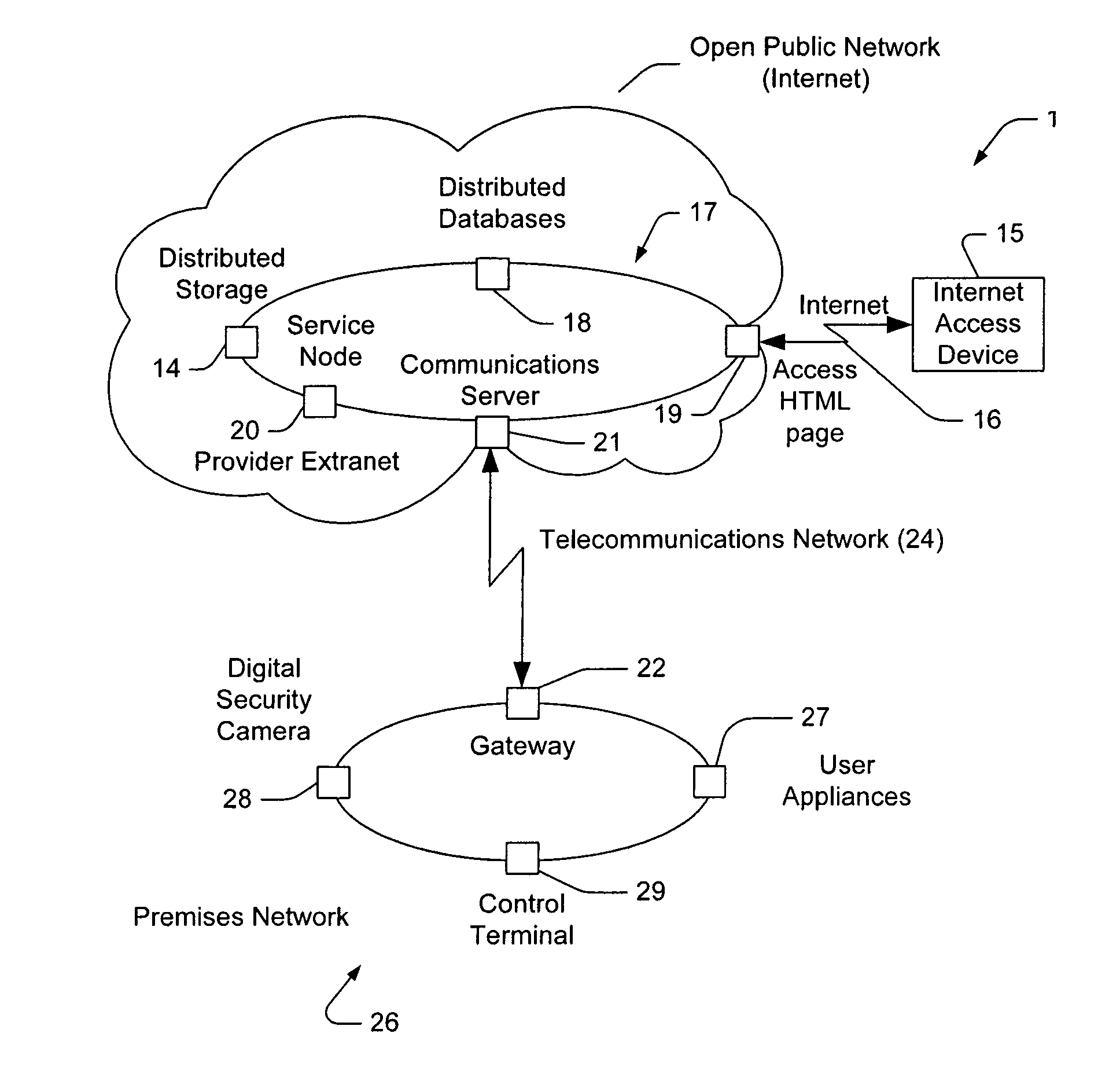
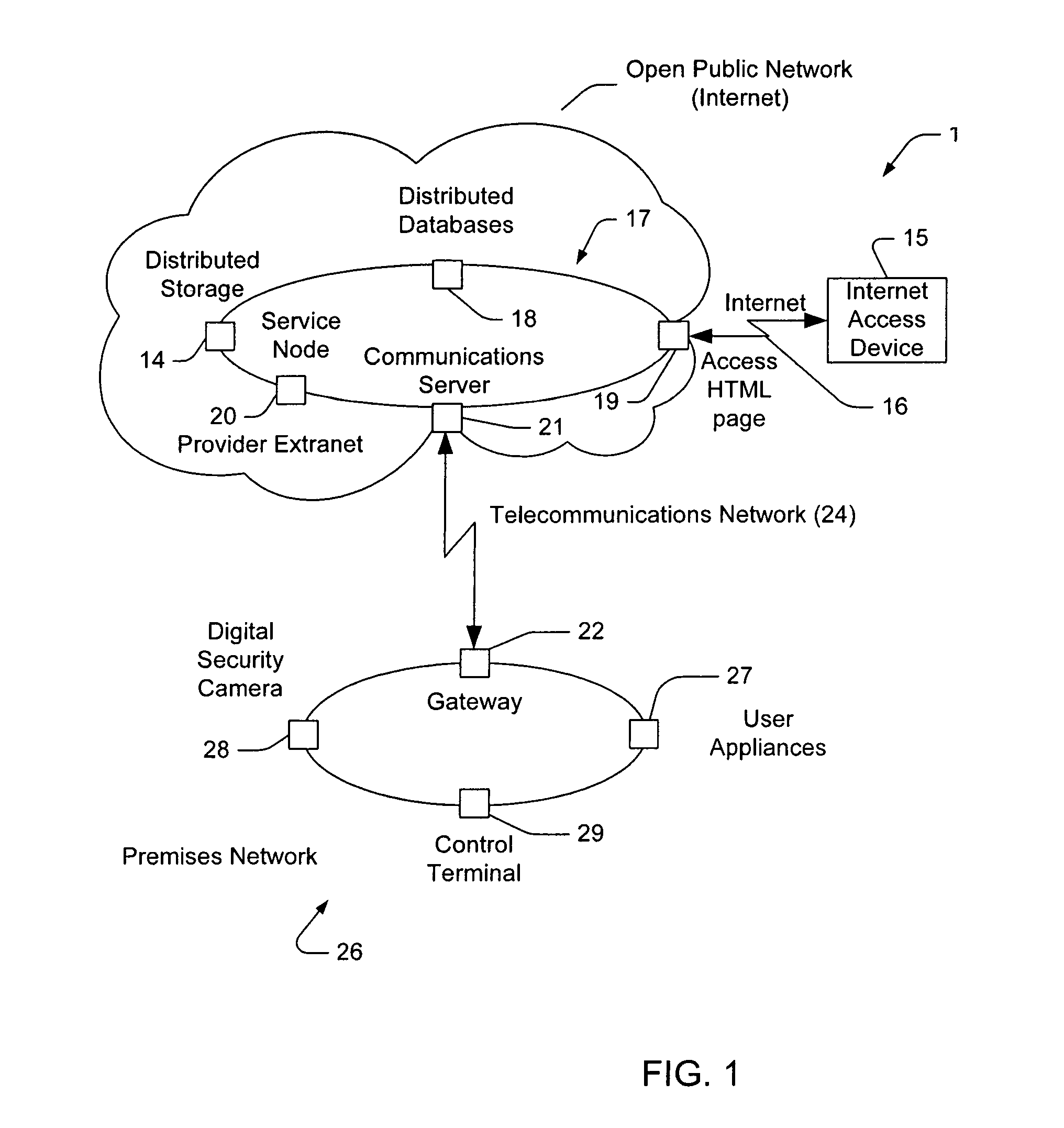
The patent describes a system that allows a control terminal to access a home network through an extranet, which is part of the Internet. The control terminal can be a flat panel display with a touch screen and a biosensor for user authentication. The data storage on the extranet ensures the integrity of surveillance data. The technical effects of the system include providing low-cost PSTN access and enabling mobility within the range of wireless transmitters attached to the user premises network.

Problems solved by technology

Typically these systems provide an on-site control panel offering input facilities and visual status display facilities, but generally must resort to non-visual monitoring and control mechanisms for remote operation.
Due to the complexity of the automation systems and the choices they afford users, such remote systems are cumbersome and limit the scope for interaction.
Another problem with current systems is the absence of a monitoring and control method that provides a geographically independent standard interface that is universally accessible and not platform or hardware dependant.
However, this requires special knowledge and telecommunications access facilities on the part of the user and is not a suitable mechanism for those individuals who are not technically literate.
Another problem with current systems, and with the system described by Corcoran, is that if the user is geographically remote to the user premises, then initiating a direct connection through the public telecommunication network is expensive, requiring a long distance or international call.
Another problem with current systems relates to the handling of alarm and surveillance data.
A problem associated with such systems is that surveillance data remains unprotected whilst retained at the site of an incursion.
Another problem with current systems relates to the cost associated with the surveillance system.
System costs for video surveillance may be prohibitive, as they are based on CCTV and VCR technology.
Methods employed to make such systems tamper-proof add to the total system cost.
Another problem associated with current surveillance systems is that they may not differentiate alarm and non-alarm conditions, and continuously record activity.
Another problem with current systems is that they do not allow, except in the case of expensive systems, a remote user, or remote authorised security personnel, to interrogate a surveillance or automation system during an alarm condition.
Another problem with existing systems is that they do not provide a facility for viewing surveillance material in relation to a user premises during non-alarm periods using standard platform independent and location independent mechanisms.

Method used


Image

  • Local and remote monitoring using a standard web browser
  • Local and remote monitoring using a standard web browser
  • Local and remote monitoring using a standard web browser

Examples


case 1

[0110] Dynamic Assignment is Achieved by Reconfiguration of End Point Router Interface Configuration Tables Service Node 20.[0111]1. A control channel is established to the end-point gateway 22 as specified in the connection profile[0112]2. The end point gateway 22 is programmed with the IP address specified in the connection profile (the IP address may be obtained dynamically by the service node 20 server from any dynamic host configuration service), and with the connection details required to establish physical connection via OSI level 1 network.[0113]3. Request for response is sent to IP address specified in connection profile of device e.g. 27-29 via end point gateway 22.[0114]4. Request for response is delivered to appropriately reconfigured interface.[0115]5. Response (either positive or negative) is received from interface of device 27-29.[0116]6. Response is relayed to Gateway 22.[0117]7. If successful user HTTP connection is redirected to remote HTTP service on gateway 22.[...

case 2

[0119] Dynamic Assignment is Achieved by Request for IP Address Assignment from Dynamic Host Configuration Service (Local to End-Point Router) Initiated by Endpoint Router Based on Connection Parameter (from the Connection Profile) Encapsulated in the Request Packet Received from the Server Node 20.[0120]1. Service Node 20 encapsulates connection parameters from connection profile in request packet which is sent to communications server 21.[0121]2. Communications server 21 detects request packet received from service node 20.[0122]3. Communications server 21 detects queries DHC server with connection parameters.[0123]4. DHC server dynamically assigns IP address for connection profile to endpoint gateway[0124]5. Endpoint router reconfigures interface using connection parameters and IP address[0125]6. Request for response is delivered to appropriately reconfigured interface.[0126]7. Response (either positive or negative) is received from interface.[0127]8. Response is relayed to Gatew...


PUM


Abstract

A home security and control system for monitoring and controlling an external environment such as a home environment comprising: an Internet browser connectable to an extranet; an extranet located external to the home environment and accessible via the Internet browser; a communications server located in the extranet and adapted to interconnect on demand with one of a series of connection gateways located in predetermined home environments; and a connection gateway located in the home environment adapted to control and / or monitor the operation of at least one security device in the home environment; wherein upon accessing a predetermined address by the Internet browser on the extranet, the communications server connects to a predetermined one of the connection gateways to control and / or monitor the operation of the security device. The extranet can ideally be implemented as a Virtual Private Network (VPN) across an Internet substrate.

Description

FIELD OF THE INVENTION[0001]The present invention relates to the area of local and remote monitoring and control, through use of a standard web browser and the InternetBACKGROUND OF THE INVENTION[0002]A communication node between data and a telecommunication networks is disclosed in PCT Patent Publication Number WO 94 / 24803 which describes a node that enables communication between users using different types of terminals, such as telephones and computers.[0003]PCT Patent Publication Number WO 98 / 19445 describes a service node between Internet networks and a telecommunications network that is used to order telephony services by means of HTML pages from a computer with a WWW browser. It also describes a method of calling a subscriber, in which the call is ordered by computer but the connection is set up between the telephones of a first and second subscriber. The service node communicates with computers connected to computer networks using the HTTP protocol. The node stores data relat...

Claims


Application Information

Patent Timeline
IPC IPC(8): H04M11/04G06F15/16H04L12/46H04L29/08H04L29/06H04L12/66H04M11/00
CPCH04L67/12H04L67/025H04L29/06H04M11/04H04L69/329H04L67/10H04L9/40G08B25/10H04L12/4641H04L12/66H04L63/0272H04L63/083H04L63/1425H04L67/14
Inventor LINDQUIST, CHARLES CAMERONLINDQUIST, TIMOTHY JOHN
Owner PORTUS SINGAPORE
Learn More