
Spark plug

a technology of spark plugs and plugs, which is applied in the field of spark plugs, can solve the problems of internal corrosion and durability deterioration, and achieve the effects of improving corrosion resistance and durability, increasing the number of cracks, and reducing the number of spark plugs

Active Publication Date: 2014-12-30
NGK SPARK PLUG CO LTD
View PDF7 Cites 1 Cited by
  • Summary
  • Abstract
  • Description
  • Claims
  • Application Information

AI Technical Summary

Benefits of technology

[0020]According to the spark plug of configuration 1, since the ground electrode is formed from a metal material in which precipitates containing at least one of an oxide, a carbide, a nitride, and an intermetallic compound are precipitated in grain boundaries, the ground electrode can be improved in corrosion resistance and durability.
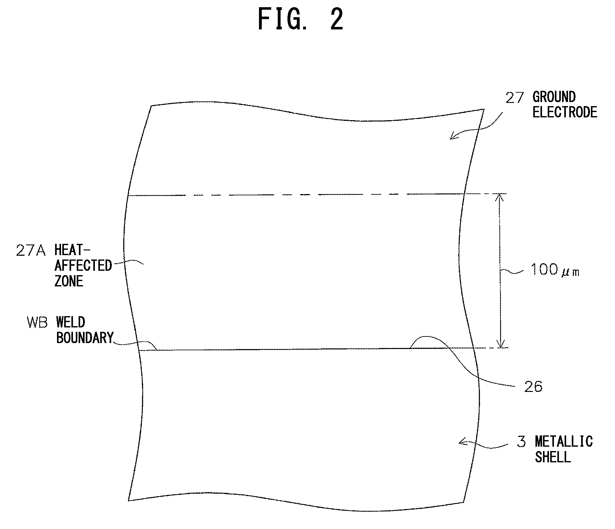
[0021]On the other hand, since a metal material used to form the ground electrode contains precipitates, the ground electrode involves a concern about deterioration in welding strength. However, according to the spark plug of configuration 1, the area occupied by the precipitates on a section of the heat-affected zone is equal to 65% or more the area occupied by the precipitates on a section of the normal zone. That is, configuration 1 is determined such that precipitates are deposited sufficiently in the heat-affected zone. Therefore, precipitates can be more reliably prevented from falling in a supersaturated state in the heat-affected zone. As a result, embrittlement of the weld zone (the heat-affected zone and its vicinity) associated with a plating process can be effectively restrained.
[0022]Meanwhile, when cracking occurs originating from a precipitate, cracking propagates between precipitates along grain boundaries. At this time, when the distance between precipitates is excessively small, cracking propagates more quickly; as a result, strength may deteriorate. In this regard, according to the spark plug of configuration 1, as viewed on a section of the heat-affected zone, the diameter of an equivalent circle of a precipitate having the greatest area among precipitates is 50 μm or less, and the shortest distance between precipitates is 2 μm or greater. That is, since configuration 1 is determined such that the distance between precipitates does not become excessively small, the propagation speed of cracking can be effectively lowered. As a result, deterioration in strength of the heat-affected zone can be more reliably prevented.
[0023]As described above, according to the spark plug of configuration 1, embrittlement of the heat-affected zone can be restrained, and deterioration in strength of the heat-affected zone can be more reliably prevented through reduction of the propagation speed of cracking. As a result, the welding strength of the ground electrode can be drastically improved.
[0024]The spark plug of configuration 2 is configured such that precipitates are precipitated in a larger amount in the heat-affected zone and is configured to ensure a larger distance between precipitates. Therefore, precipitates can be more reliably prevented from falling in a supersaturated state in the heat-affected zone, and the propagation speed of cracking can be more effectively lowered.
[0025]The spark plug of configuration 3 is configured such that the diameter of an inscribed equivalent circle of a precipitate having the greatest area among the precipitates on a section of the heat-affected zone is equal to 85% or more the diameter of an equivalent circle of a precipitate having the greatest area among the precipitates on a section of the normal zone. That is, configuration 3 is determined such that precipitates are precipitated sufficiently in the heat-affected zone. Thus, precipitates can be more reliably prevented from falling in a supersaturated state in the heat-affected zone. As a result, configuration 3 yields actions and effects similar to those yielded by the above configuration 1.

Problems solved by technology

Accordingly, the ground electrode is apt to suffer a problem that crystals of a metal material used to form the ground electrode coarsen (so-called grain growth), potentially resulting in internal corrosion and a deterioration in durability.

Method used


Image

  • Spark plug
  • Spark plug
  • Spark plug

Examples


Embodiment Construction

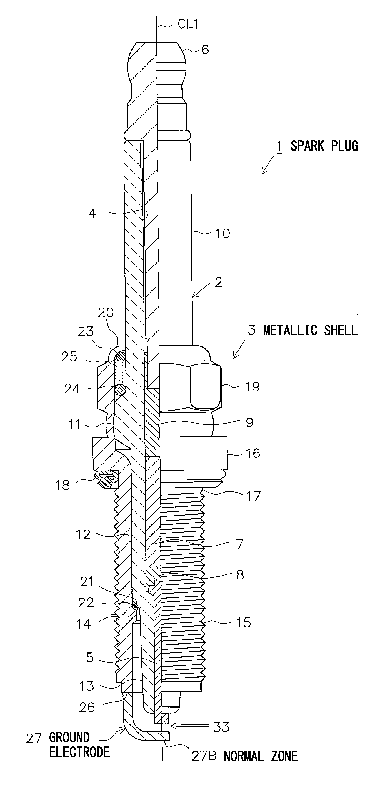
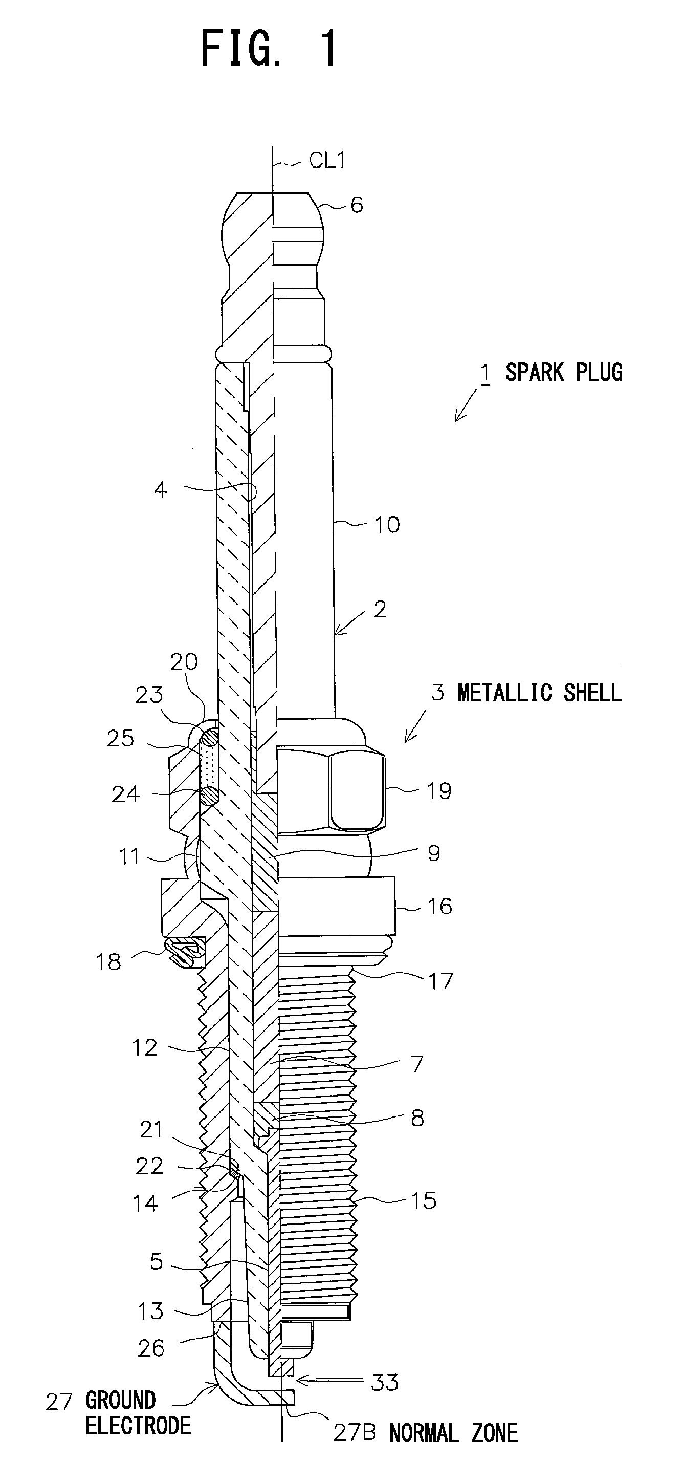
[0032]An embodiment of the present invention will next be described with reference to the drawings. FIG. 1 is a partially cutaway front view showing a spark plug 1. In FIG. 1, the direction of an axis CL1 of the spark plug 1 is referred to as the vertical direction in the drawing. In the following description, the lower side of the spark plug 1 in FIG. 1 is referred to as the forward side of the spark plug 1, and the upper side as the rear side.

[0033]The spark plug 1 includes a ceramic insulator 2 and a tubular metallic shell 3, which holds the ceramic insulator 2 therein.

[0034]The ceramic insulator 2 is formed from alumina or the like by firing, as well known in the art. The ceramic insulator 2, as viewed externally, includes a circular columnar rear trunk portion 10 formed on the rear side; a large-diameter portion 11, which is located forward of the rear trunk portion 10 and projects radially outward; an intermediate trunk portion 12, which is located forward of the large-diamete...


PUM

PropertyMeasurementUnit
diameteraaaaaaaaaa
diameteraaaaaaaaaa
diameteraaaaaaaaaa

Abstract

A spark plug (1) includes a metallic shell (3) and a ground electrode (27) resistance-welded to the metallic shell (3). The ground electrode (27) is formed from a metal material in which precipitates PR containing at least one of an oxide, an intermetallic compound, etc., are precipitated in grain boundaries. The diameter of an equivalent circle of a precipitate PR having the greatest area is 50 μm or less, and the shortest distance between the precipitates PR is 2 μm or greater. The area occupied by the precipitates PR on the section of the heat-affected zone 27A is equal to 65% or more the area occupied by the precipitates PR (the diameter of an equivalent circle of a precipitate PR having the greatest area) on a section of the normal zone 27B.

Description

CROSS REFERENCE TO RELATED APPLICATIONS[0001]This application is a National Stage of International Application No. PCT / JP2010 / 006899 filed Nov. 26, 2010, and which claims benefit to Japanese Patent Application No. 2010-081033 filed Mar. 31, 2010 and Japanese Patent Application No. 2010-203271 filed Sep. 10, 2010, the contents of which are incorporated herein by reference in their entirety.TECHNICAL FIELD[0002]The present invention relates to a spark plug for use in an internal combustion engine or the like.BACKGROUND ART[0003]A spark plug is mounted to, for example, an internal combustion engine (an engine) for igniting an air-fuel mixture contained in a combustion chamber. Generally, a spark plug includes an insulator having an axial bore; a center electrode inserted into a forward end portion of the axial bore; a metallic shell provided externally of the outer circumference of the insulator; and a ground electrode which is resistance-welded to a forward end portion of the metallic...

Claims


Application Information

Patent Timeline
Patent Type & Authority Patents(United States)
IPC IPC(8): B23K35/30B23K35/02H01T13/39H01T13/32C22C19/03B23K11/00
CPCH01T13/32B23K35/3033H01T13/39B23K11/002C22C19/03B23K35/0261
Inventor YOSHIMOTO, OSAMUTANAKA, TOMO-OKACHIKAWA, NORIHIDE
Owner NGK SPARK PLUG CO LTD
Learn More