
Electrode structure and method of manufacturing the same, and battery and method of manufacturing the same

a technology of electromechanical structure and manufacturing method, applied in the direction of sustainable manufacturing/processing, cell components, final product manufacturing, etc., can solve the problems of insufficient performance or yield of a battery using the insufficient caulking method in terms of securing electrical conduction between, and insufficient caulking method in related arts, so as to prevent variations in electrical performance such as electrical conductivity, and sufficient electrical conduction

Active Publication Date: 2015-01-13
MURATA MFG CO LTD
View PDF7 Cites 1 Cited by
  • Summary
  • Abstract
  • Description
  • Claims
  • Application Information

AI Technical Summary

Benefits of technology

The patent text describes an electrode structure and method of manufacturing it that prevents variations in electrical performance and stabilizes battery performance. The electrode has a hole formed by penetrating the electrode lead and the electrode, which is then folded back in a direction away from the hole. This ensures uniform thickness of the active material layer and prevents variations in electrical performance. The method of manufacturing the electrode involves folding the electrode lead and electrode around the hole in a penetrating direction and then folding them back in a direction away from the hole. This ensures sufficient contact between the electrode lead and current collector, preventing variations in electrical performance. The use of this electrode structure and method of manufacturing results in stabilized performance and improved yields for batteries.

Problems solved by technology

However, a caulking method in related arts does not have an issue in terms of fixing the electrode lead to the electrode; however, the caulking method in related arts is not sufficient in terms of securing electrical conduction between them.
It is because when an active material layer is inserted between the current collector and the electrode lead, the active material layer interferes with electrical conduction between them.
Thereby, in the caulking method in related arts, electrical performance such as electrical conductivity easily varies due to a bonding state between the electrode and the electrode lead, so there is an issue that the performance or yields of a battery using the caulking method in related arts is not sufficient.

Method used


Image

  • Electrode structure and method of manufacturing the same, and battery and method of manufacturing the same
  • Electrode structure and method of manufacturing the same, and battery and method of manufacturing the same
  • Electrode structure and method of manufacturing the same, and battery and method of manufacturing the same

Examples


first embodiment

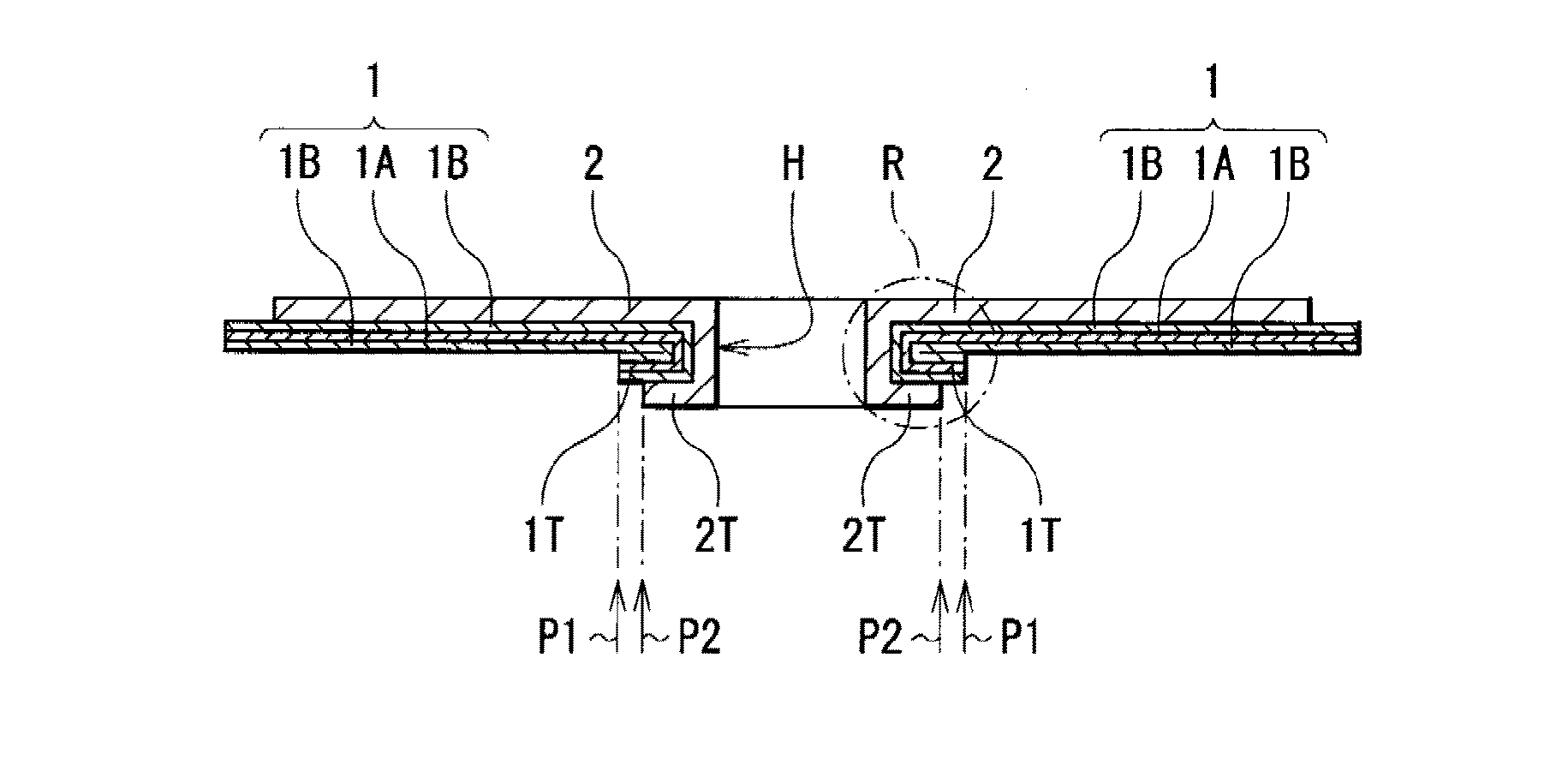
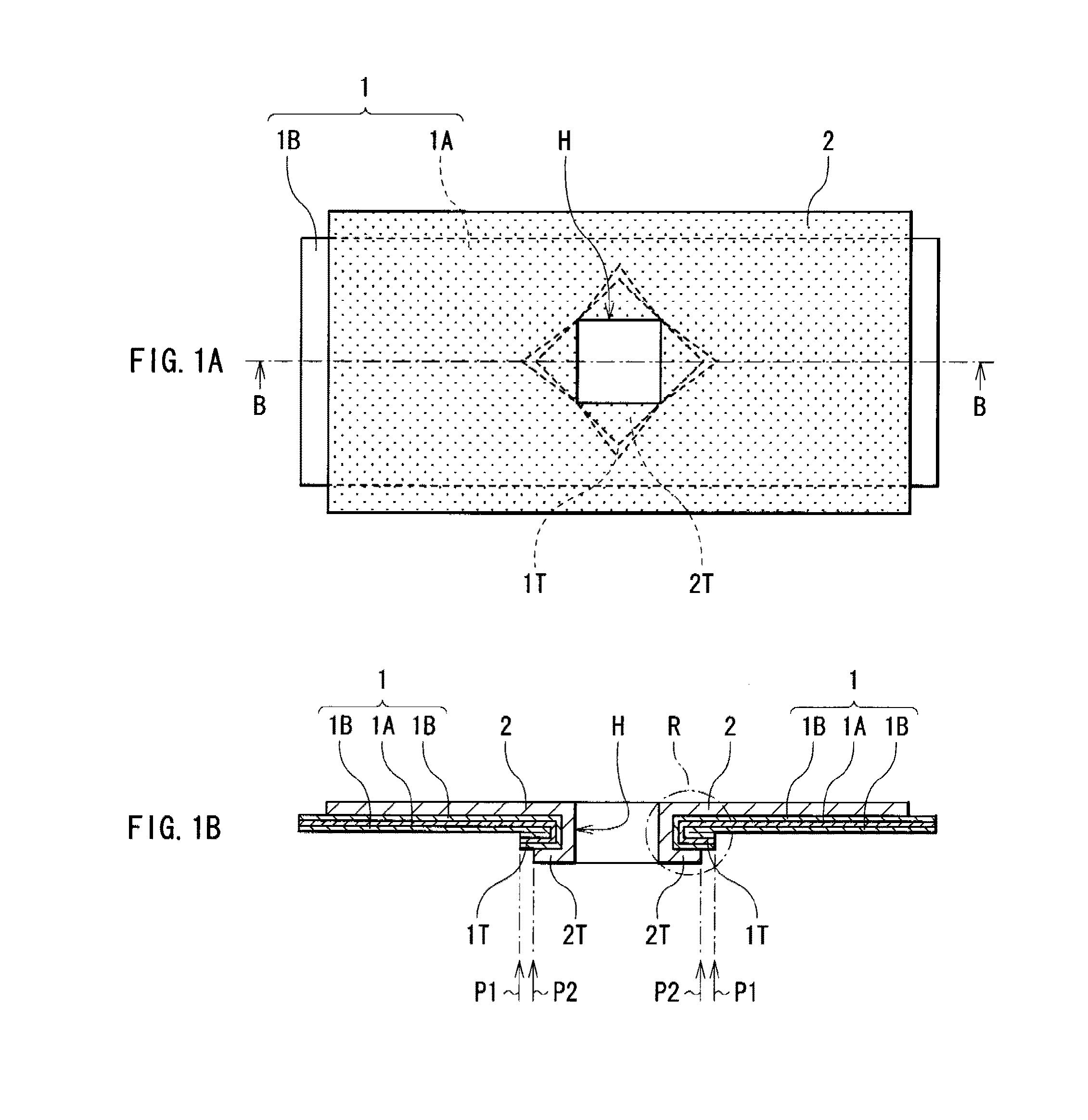
[0049]FIGS. 1A and 1B show the configuration of an electrode structure according to a first embodiment of the invention, and FIG. 1A shows a plan view and FIG. 1B shows a sectional view taken along a line B-B of FIG. 1A. Hereinafter a dimension in the long side direction of the electrode structure is referred to as “length”, and a dimension in the short side direction is referred to as “width”.

[0050]The electrode structure is used as a cathode structure or an anode structure in an electrochemical device such as a battery, and as shown in FIGS. 1A and 1B, the electrode structure includes an electrode 1 and an electrode lead 2 attached to the electrode 1. The electrode 1 includes a current collector 1A and an active material layer 1B arranged on the current collector 1A, and the electrode lead 2 is arranged on the active material layer 1B.

[0051]The current collector 1A is made of a metal material having good electrical conductivity, electrochemical stability and mechanical strength, f...

second embodiment

[0080]FIG. 11 shows the configuration of an electrode structure according to a second embodiment of the invention, and shows a sectional view corresponding to FIG. 1B. In FIG. 11, like components are denoted by like numerals as of the first embodiment.

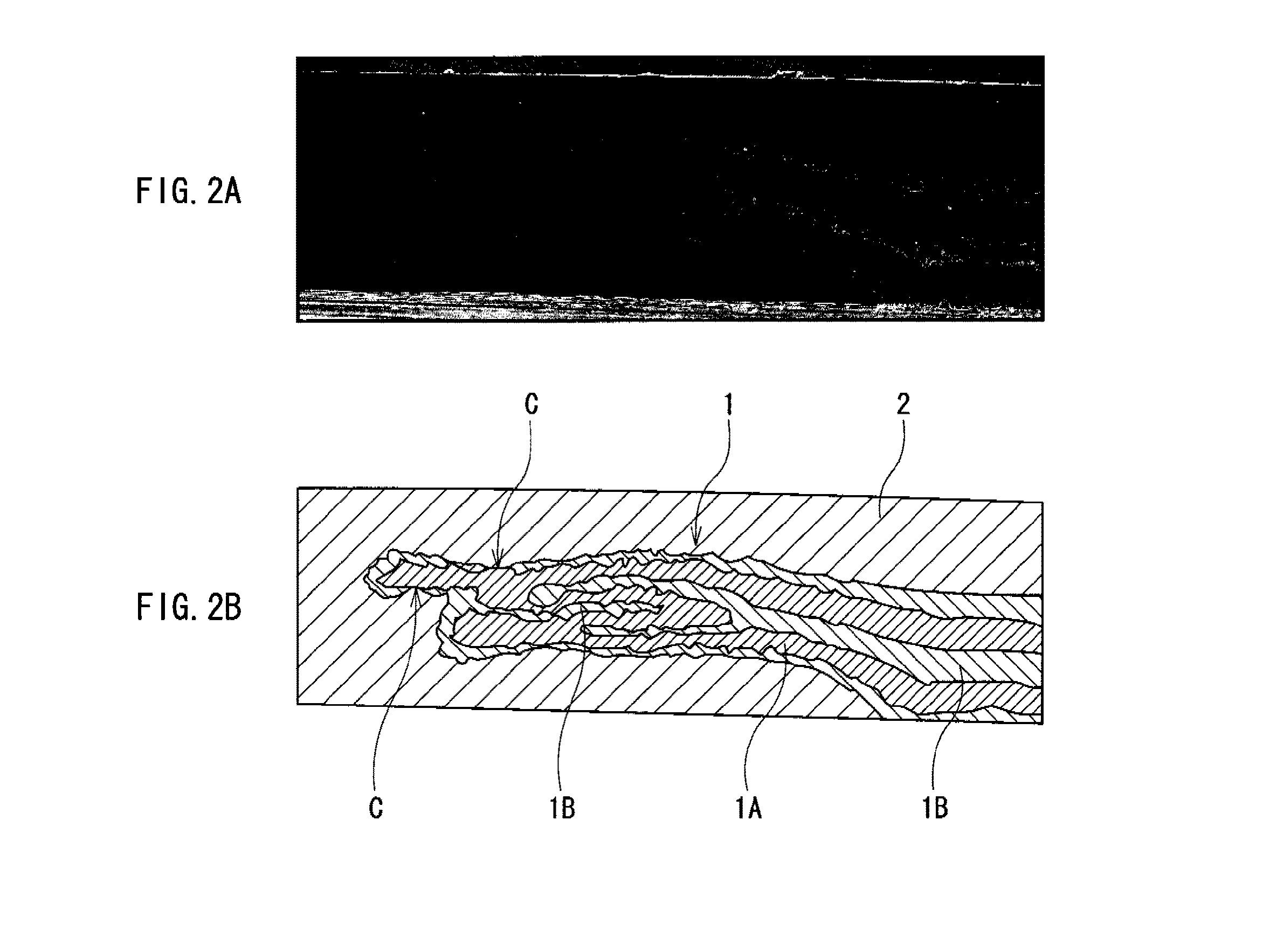
[0081]The electrode structure has the same configuration as that of the electrode structure according to the first embodiment, except that the electrode 1 and the electrode lead 2 are folded back around the hole H in a direction away from the hole H so that the electrode 1 is placed inside, and the folded-back portion 2T of the electrode lead 2 makes contact with the current collector 1A exposed at a tip of the folded-back portion 1T of the electrode 1. In other words, the current collector 1A and the electrode lead 2 are electrically conducted at an exposed point of the current collector 1A exposed at the tip of the folded-back portion 1T as the contact point C. In this case, the tip (the position P2) of the folded-back portion 2T of ...

third embodiment

[0089]FIG. 16 shows the configuration of an electrode structure according to a third embodiment of the invention, and shows a sectional view corresponding to FIG. 1B. In FIG. 16, like components are denoted by like numerals as of the first embodiment.

[0090]The electrode structure has the same configuration as that of the electrode structure according to the first embodiment, except that the electrode 1 and the electrode lead 2 are folded back around the hole H in a direction away from the hole H so that the electrode lead 2 is placed inside, and the folded-back portion 2T of the electrode lead 2 makes contact with the current collector 1A exposed at the tip of the folded-back portion 1T of the electrode 1. In other words, the current collector 1A and the electrode lead 2 are electrically conducted at an exposed point of the current collector 1A exposed at the tip of the folded-back portion 1T as the contact point C. In this case, the tip (the position P2) of the folded-back portion ...


PUM

PropertyMeasurementUnit
widthaaaaaaaaaa
lengthaaaaaaaaaa
thicknessaaaaaaaaaa

Abstract

An electrode capable of preventing variations in electrical performance to stabilize performance and improve yields is provided. An electrode structure includes: an electrode including an current collector and an active material layer arranged on the current collector; and an electrode lead arranged on the active material layer, wherein a hole is arranged so as to penetrate the electrode and the electrode lead, and the electrode and the electrode lead are folded back around the hole in a direction away from the hole so that the electrode is placed inside, and the thickness of the active material layer in a region where the electrode lead is not arranged is uniform, and the thickness of the active material layer in a region where the electrode lead is arranged is nonuniform.

Description

CROSS REFERENCES TO RELATED APPLICATIONS[0001]The present invention contains subject matter related to Japanese Patent Application JP 2007-045299 filed in the Japanese Patent Office on Feb. 26, 2007, the entire contents of which being incorporated herein by reference.BACKGROUND OF THE INVENTION[0002]1. Field of the Invention[0003]The present invention relates to an electrode structure including an electrode and an electrode lead and a method of manufacturing the same, and a battery including an electrode structure and a method of manufacturing the same.[0004]2. Description of the Related Art[0005]In recent years, portable electronic devices such as camera-integrated VTRs (videotape recorders), cellular phones, or laptop computers are widely used, and size and weight reduction in the portable electronic devices and an increase in longevity of the portable electronic devices have been strongly demanded. Accordingly, as power sources for the portable electronic devices, the development...

Claims


Application Information

Patent Timeline
Patent Type & Authority Patents(United States)
IPC IPC(8): H01M4/02H01M4/04H01M4/13H01M4/139H01M10/0566H01M50/534H01M50/536
CPCH01M2/26H01M4/02H01M4/139H01M10/052Y02E60/122Y10T29/4911Y02E60/10Y02P70/50H01M50/536H01M50/534H01M4/13H01M50/528
Inventor SHIBATA, HIRONORISASAKI, AKIRASOJI, KAZUHIKO
Owner MURATA MFG CO LTD
Learn More