Hydrostatic drive system

a drive system and hydrostatic technology, applied in the direction of fluid couplings, couplings, transportation and packaging, etc., can solve the problems of corresponding shifting losses and corresponding inert response behavior, and achieve low flow losses, good response behavior, and avoid hysteresis phenomena

Active Publication Date: 2015-02-24
HYDAC TECH GMBH
View PDF12 Cites 40 Cited by
  • Summary
  • Abstract
  • Description
  • Claims
  • Application Information

AI Technical Summary

Benefits of technology

[0003]An object of the invention is to provide an improved drive system characterized by an especially simple structure of the hydraulic circuit and at the same time by an operating behavior improved relative to the prior art.
[0004]According to the invention, this object is basically achieved by a hydrostatic drive system having a valve device by which the segment of each working line extending to at least one drive unit can be separated in terms of operation. By separating these segments of the two working lines, the hydraulic circuit is divided into two component circuits, specifically into a part of the circuit containing the hydraulic pump and an accumulator part containing at least one drive unit and the hydraulic accumulator. In the normal drive state, that is, without acceleration or braking processes, there is no interruption of the working lines to the drive unit so that the drive unit is supplied from the hydraulic pump via the working lines. If an acceleration or braking process is to take place, the connections to the drive device are separated by the valve device. This separation means that the accumulator part is separated from the hydraulic circuit, and for acceleration and braking processes therefore only the portion of lines and hydraulic components that belongs to the accumulator part is involved. This arrangement yields not only the advantage of a good response behavior as a result of the stiffness of the line system encompassing only the accumulator part, thereby avoiding hysteresis phenomena, but the arrangement is also characterized by low flow losses due to the reduced line volumes through which the participating volumes are flowing.

Problems solved by technology

As a result, corresponding shifting losses and a correspondingly inert response behavior result.

Method used


Image

  • Hydrostatic drive system
  • Hydrostatic drive system

Examples


Embodiment Construction

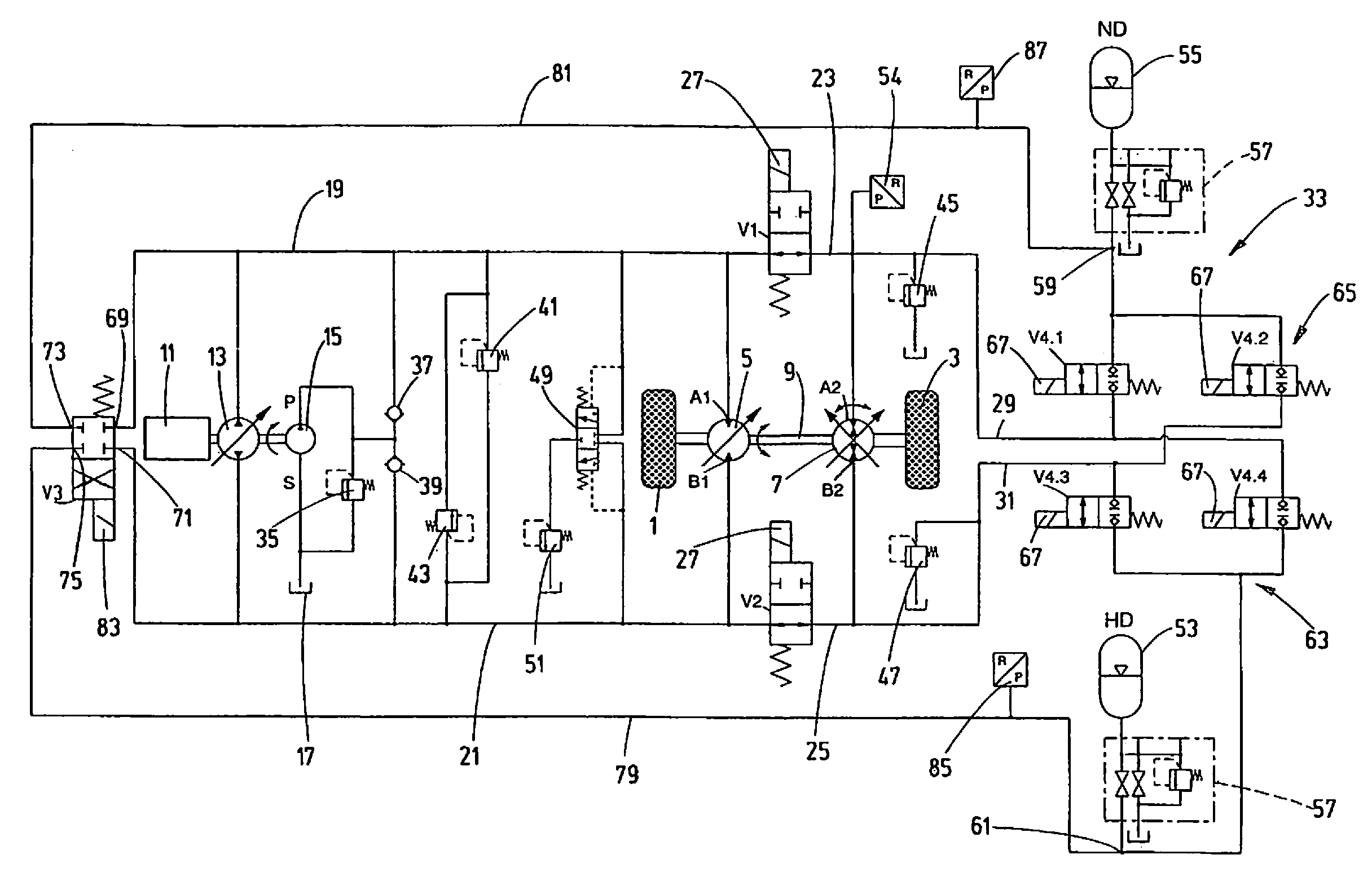
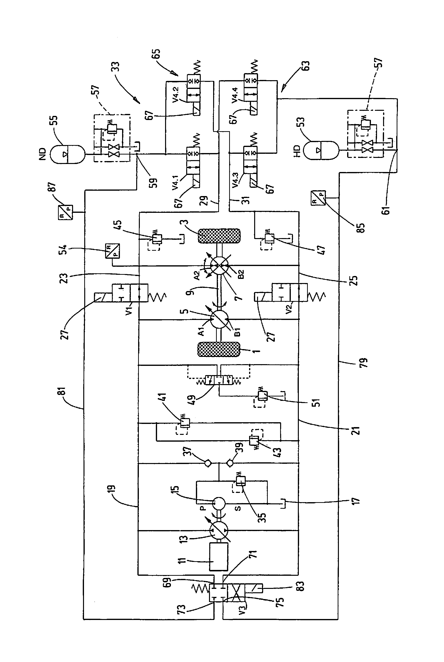
[0015]The invention is described using the example of a traveling mechanism intended, for example, for use in buses, with two drive units 5 and 7 being connected to one gear set 1 and 3 each. The first drive unit 5 is a fixed displacement motor that can be operated in two directions of rotation according to two volumetric flow directions. The second drive unit 7 is formed by an adjustable motor pump, likewise for two volumetric flow directions, according to the two directions of rotation. In this exemplary embodiment, the first drive unit 5 and second drive unit 7 are directly coupled mechanically via a connecting shaft 9.

[0016]For the energy supply of the system, a primary drive is provided by an internal combustion engine, in this exemplary embodiment in the form of a diesel engine11 that drives a hydraulic pump 13 in the form of an adjustable pump that, for the same direction of rotation, can deliver in two volumetric flow directions. A feed pump 15 in the form of a fixed displac...


PUM


Abstract

A hydrostatic drive system has a motor-driven hydraulic pump (1) connected to at least one hydraulic drive unit (7) by a first working line (19) and a second working line (21) forming a hydraulic circuit. The drive unit is connected to a gear set (1, 3). A first hydraulic accumulator (53) for accumulating pressure energy can be connected to one of the working lines (19, 21). A second hydraulic accumulator (55) can be connected to the other working line (19, 21). A valve device (V1, V2) permits the segment (23, 25) of each working line (19 or 21) extending to the drive unit (7) to be separated to separate an accumulator part (33) from the part of the circuit with the hydraulic pump (13). The accumulator part includes the hydraulic accumulators (53, 55) and at least one drive unit.

Description

FIELD OF THE INVENTION[0001]The invention relates to a hydrostatic drive system having a motor-drivable hydraulic pump that can be connected to at least one hydraulic drive unit by first and second working lines forming a hydraulic circuit. One hydraulic accumulator, for recovery of stored pressure energy, can be connected to one of the working lines, and a second hydraulic accumulator can be connected to the other working line.BACKGROUND OF THE INVENTION[0002]Hydrostatic drives of this type, as are shown, for example, in document WO 2007 / 079935 A1, are often used in commercial vehicles like buses or mobile machinery. These drive systems offer the possibility of storing a part of the kinetic energy as pressure energy during braking processes and then recovering it to support acceleration processes. In this respect, the prior art provides for at least one drive unit to be set up as a hydraulic motor in the form of an adjustable motor-pump unit so that the hydraulic motor delivers hyd...

Claims


Application Information

Patent Timeline
Patent Type & Authority Patents(United States)
IPC IPC(8): F16H61/448B60K6/12F16H61/4096
CPCF16H61/4096B60K6/12F16H61/448Y02T10/6208Y02T10/62
Inventor BALTES, HERBERTBAUER, FRANK
Owner HYDAC TECH GMBH
Why Eureka
Try Eureka