Methods of manufacturing end effectors for energy-based surgical instruments

a technology of end effectors and surgical instruments, applied in the field of surgical instruments, can solve problems such as damage to devices and/or surrounding tissu

Inactive Publication Date: 2015-02-24
TYCO HEALTHCARE GRP LP
View PDF27 Cites 185 Cited by
  • Summary
  • Abstract
  • Description
  • Claims
  • Application Information

AI Technical Summary

Problems solved by technology

However, electrosurgical electrodes having irregular edges formed during the deposition process may cause uncontrolled arcing upon application of energy thereto, which may ultimately damage the device and / or surrounding tissue.

Method used


Image

  • Methods of manufacturing end effectors for energy-based surgical instruments
  • Methods of manufacturing end effectors for energy-based surgical instruments
  • Methods of manufacturing end effectors for energy-based surgical instruments

Examples


Embodiment Construction

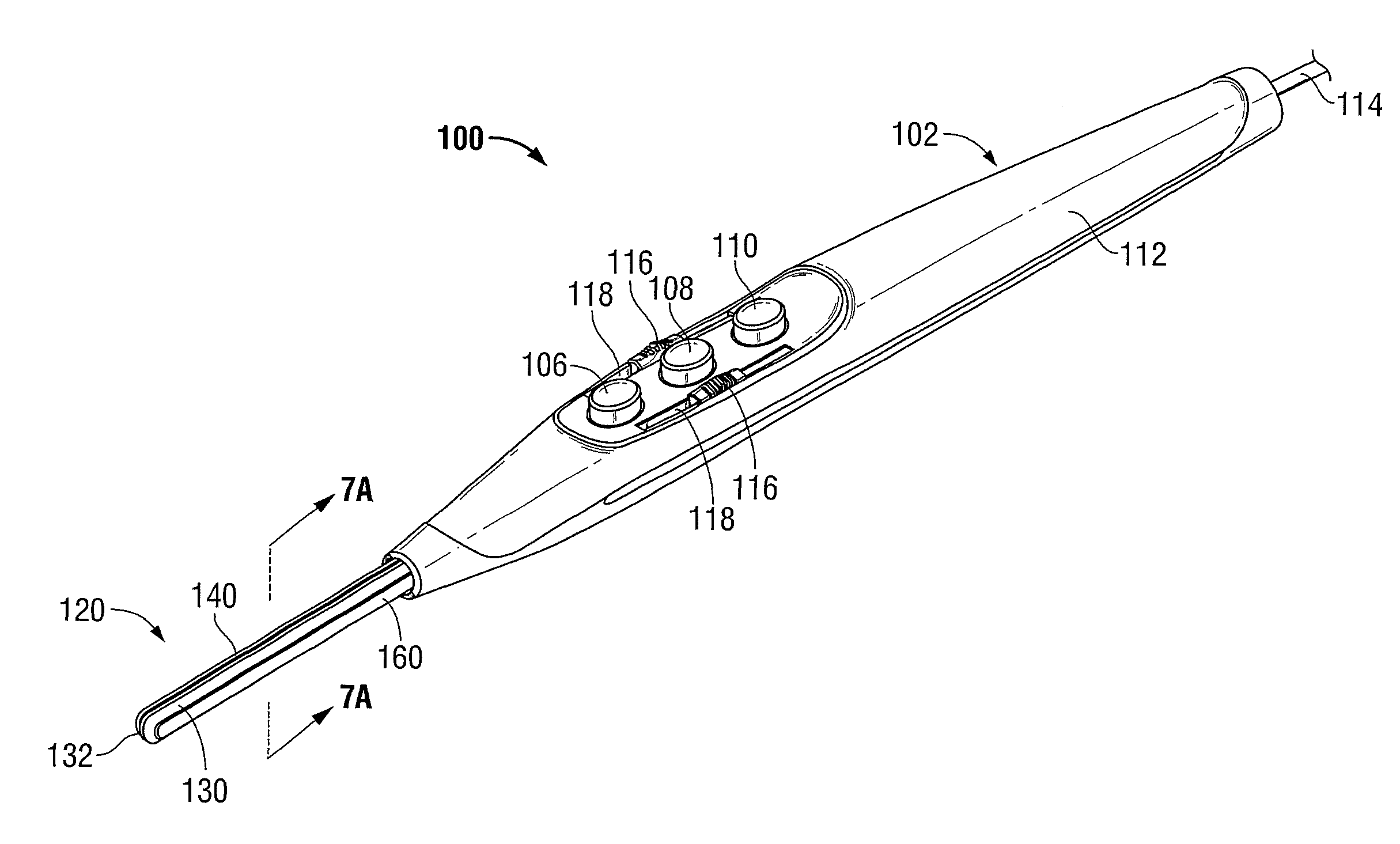
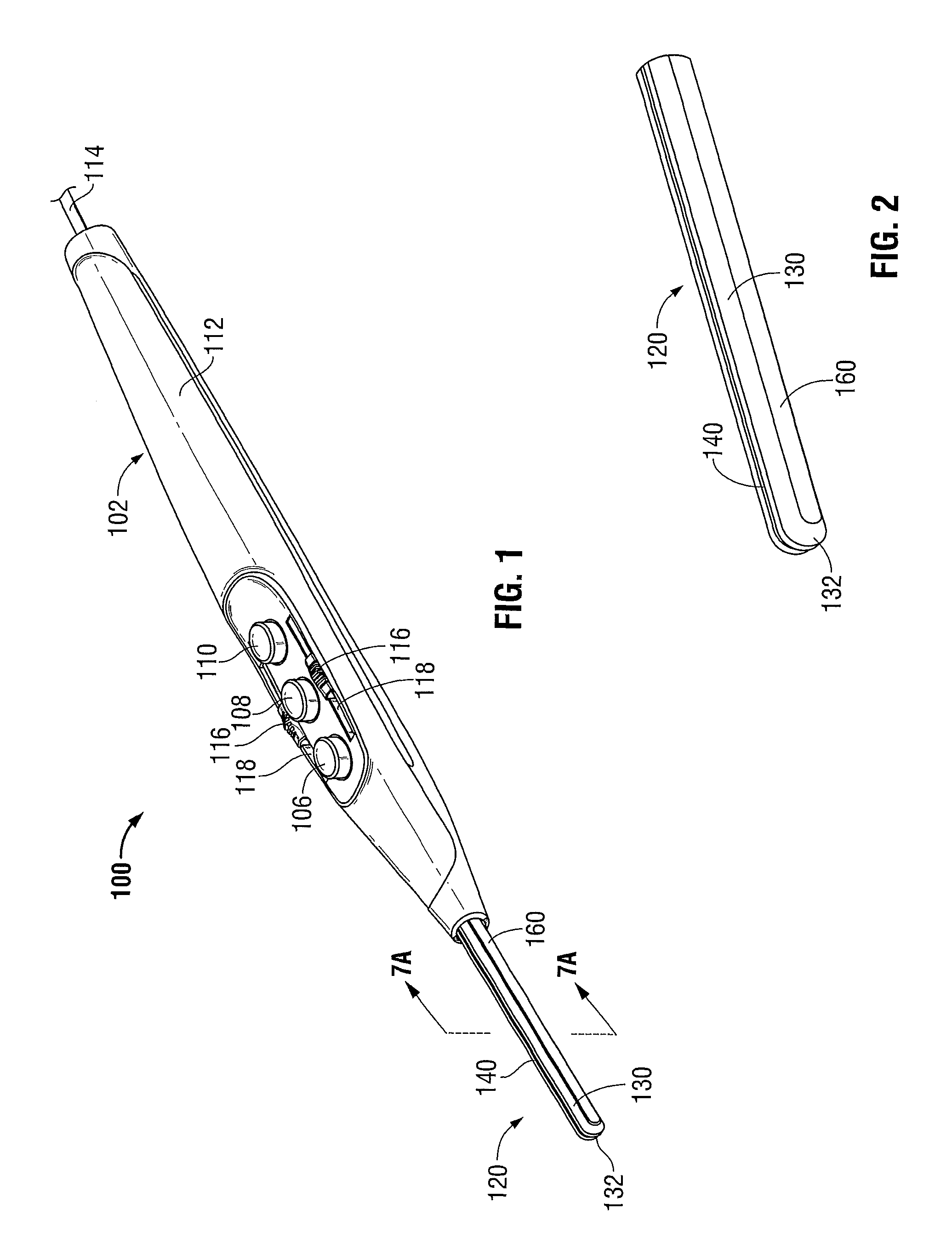
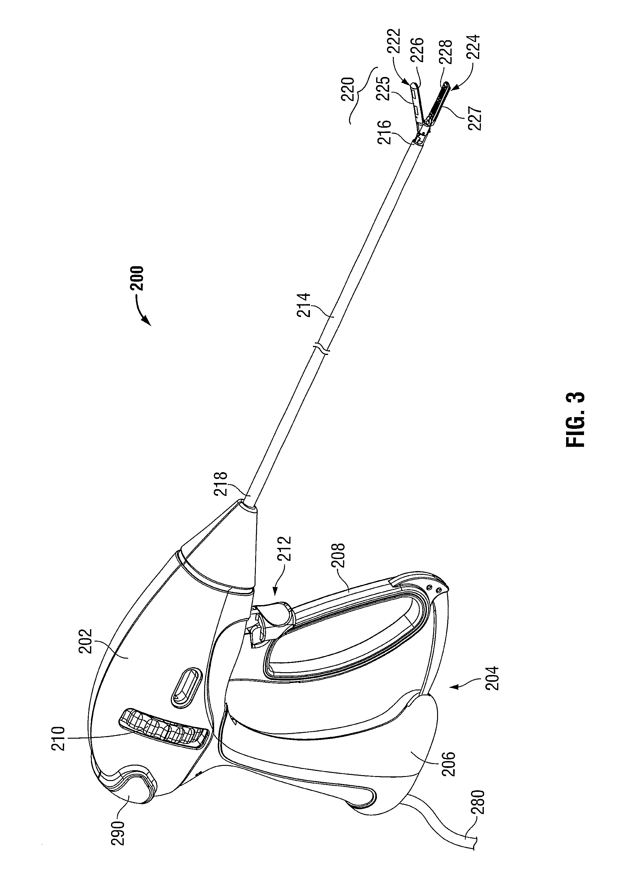
[0039]The operating features and inter-cooperating components of energy-based surgical instruments 100, 200 provided in accordance with the present disclosure are shown in the figures and are described hereinbelow. More specifically, although only an electrosurgical pencil 100 (FIGS. 1-2) and an electrosurgical forceps 200 (FIGS. 3-4) are shown, the present disclosure is equally applicable for use in conjunction with any energy-based surgical instrument having an end effector including one of more electrodes configured to conduct energy to tissue to electrically treat tissue. Obviously, different mechanical and electrical considerations apply to each particular type of instrument; however, the novel aspects with respect to the end effectors and the manufacture thereof remain generally consistent regardless of the particular type of instrument used. For the purposes herein, electrosurgical pencil 100 (FIGS. 1-2) and electrosurgical forceps 200 (FIGS. 3-4) are generally described.

[004...


PUM

PropertyMeasurementUnit
viscosityaaaaaaaaaa
electrically-insulativeaaaaaaaaaa
electrically-conductiveaaaaaaaaaa

Abstract

A method of manufacturing an end effector for a surgical instrument includes providing a substrate wherein at least an outer periphery of the substrate is formed from an electrically-insulative material. The method further includes forming at least one ridge on the outer periphery of the substrate and depositing an electrically-conductive material onto the at least one ridge to form at least one electrode.

Description

BACKGROUND[0001]1. Technical Field[0002]The present disclosure relates to surgical instruments and, more particularly, to methods of manufacturing electrosurgical instruments capable of electrically treating tissue.[0003]2. Background of Related Art[0004]Various different processes are employed for depositing conductive film coatings, or inks, onto a substrate. Such processes include atomic layer chemical vapor deposition, combustion chemical vapor deposition, hot wire chemical vapor deposition, rapid thermal chemical vapor deposition, aerosol assisted chemical vapor deposition, direct liquid injection chemical vapor deposition, plasma-enhanced chemical vapor deposition, microwave plasma-assisted chemical vapor deposition, laser chemical vapor deposition, pressurized chemical vapor deposition, vapor phase epitaxy, cathodic arc deposition, electron beam physical vapor deposition, evaporative physical vapor deposition, pulsed laser physical vapor deposition, sputter physical vapor dep...

Claims


Application Information

Patent Timeline
Patent Type & Authority Patents(United States)
IPC IPC(8): A61L33/00
CPCA61B18/1442A61B18/149A61B2018/00107A61B18/14
Inventor PODHAJSKY, RONALD J.DARROW, WILLIAM S.AMBROSIUS, KRISTEL L.
Owner TYCO HEALTHCARE GRP LP
Why Eureka
Try Eureka