Maximum power point tracking method, photovoltaic system controller and photovoltaic system

a photovoltaic system and tracking method technology, applied in the direction of ac network voltage adjustment, dc source parallel operation, instruments, etc., can solve the problems of power point oscillation around the maximum power point, slow power point, and even deviation from the maximum power point of the photovoltaic system, etc., to achieve accurate estimation

Inactive Publication Date: 2015-02-24
III HLDG 6
View PDF6 Cites 4 Cited by
  • Summary
  • Abstract
  • Description
  • Claims
  • Application Information

AI Technical Summary

Benefits of technology

[0019]In this method, relatively large changes in the output power of the photovoltaic array, which are indicative of changes in illumination levels, and which shift the operating point of the photovoltaic system relatively far from its MPP are compensated in a two-step process, in which the operating voltage of a previously established MPP is used as a reference voltage to bring the operating point of the photovoltaic system in the vicinity of its adjusted MPP, after which a fine-tuning step is used, e.g. using a P&O or INC algorithm to find the adjusted MPP. For smaller changes of the in the output power of the photovoltaic array, the reference voltage application step may be skipped; in other words, relatively small changes in the operating point may be compensated using fine-tuning algorithms only. This MPP tracking method of the present invention has the advantage that can more rapidly converge to an adjusted MPP compared to P&O and INC methods for large changes in the illumination conditions of the photovoltaic system, whereas compared to the CV method, an improved efficiency is achieved because the tracking of the variation in power output does not require the frequent measurement of the open circuit voltage of the photovoltaic system.
[0021]Preferably, detecting said change in power level comprises detecting said change as a function of the delay between subsequent samples. In other words, by determining the differential power output (dP / dt) of the photovoltaic system, a constant voltage monitoring approach can be adopted without requiring the frequent measurement of the open circuit voltage, thereby limiting the disruptions to the charging of the battery of the photovoltaic system.
[0024]The combination of an increase-decrease-increase fine-tuning cycle or a decrease-increase-decrease fine-tuning cycle of the duty cycle, e.g. the pulse width of the DC voltage-DC voltage converter, with a reduction in step size between cycles leads to a rapid convergence to the MPP of the photovoltaic system.
[0027]In another embodiment, the step of tracking the power output of the photovoltaic system following said adjusting step comprises performing a two-point power output measurement for determining a differential power output of the photovoltaic system; and initiating said adjusting step if the differential power output lies below a second threshold. This has the advantage that the fine-tuning of the duty cycle of the DC voltage-DC voltage converter is only performed when the illumination levels to which the photovoltaic cells are exposed exhibit no substantial variations, thus reducing the risk of the photovoltaic system entering a mode of operation in which the power point oscillates around the MPP.
[0028]The method may further comprise performing a two-point power output measurement for determining a differential power output of the photovoltaic system during said fine-tuning; and restarting said fine-tuning upon said determined differential power output exceeding a third threshold. In this embodiment, a fine-tuning process is aborted and restarted if during the fine-tuning a substantial shift in the power output, indicative of a change in illumination levels, is detected. This prevents the MPP tracking to diverge from the MPP due to such sudden changes in illumination levels, which shift the MPP away from its previous location.
[0030]In accordance with yet another aspect of the present invention, there is provided a photovoltaic system, comprising the photovoltaic system controller of the present invention, the system further comprising at least one photovoltaic cell having an output conductively coupled to an input of the DC voltage-DC voltage converter. Such a photovoltaic system benefits from an improved tracking of the MPP under varying conditions, thereby improving the efficiency of the photovoltaic system.

Problems solved by technology

Secondly, with supplies of fossil fuels, and in particular oil, expected to run out in the foreseeable future, alternative energy supplies must be found for future generations.
It is well-known that if a load is directly connected to the output of a photovoltaic system, the arrangement operates at a less than optimal efficiency.
A drawback of the P&O algorithm is that its convergence to the maximum power point can be slow, and that shifts in the maximum power point during execution of the algorithm can cause the power point of the photovoltaic system to oscillate around the maximum power point, or even diverge from the maximum power point.
Although the INC algorithm has an improved performance compared to the P&O algorithm under rapidly changing irradiance, it is sensitive to noise and quantization errors, which can cause the system's operating point to oscillate around the maximum power point.
A drawback of this algorithm is that the MPP voltage is not always a fixed percentage of the open circuit voltage, as it depends on manufacturing process, quality of materials and other factors, and therefore requires frequent measurement of the open-circuit voltage in order to accurately track MPP, as the MPP can vary quite often due to changes in e.g. irradiance, temperature and partial shadowing.
During the open-circuit voltage measurement, the battery of the photovoltaic system cannot be charged, i.e. the power output of the photovoltaic cell array is lost, thereby reducing the efficiency of the photovoltaic system.

Method used


Image

  • Maximum power point tracking method, photovoltaic system controller and photovoltaic system
  • Maximum power point tracking method, photovoltaic system controller and photovoltaic system
  • Maximum power point tracking method, photovoltaic system controller and photovoltaic system

Examples


Embodiment Construction

[0034]Embodiments of the invention are described in more detail and by way of non-limiting examples with reference to the accompanying drawings, wherein

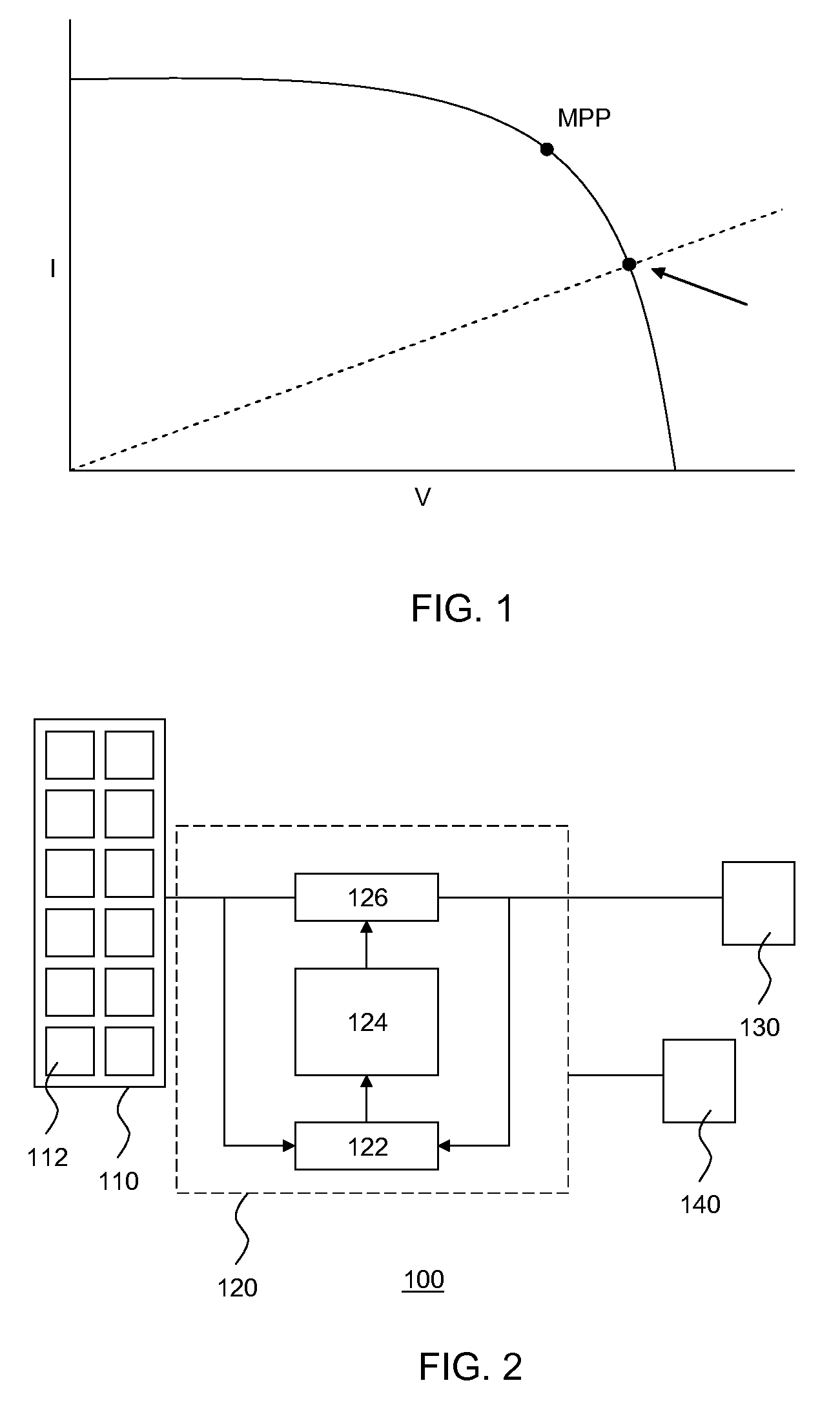
[0035]FIG. 1 depicts an IV curve of a photovoltaic system having a load directly coupled to its output;

[0036]FIG. 2 schematically depicts a photovoltaic (PV) system in accordance with an embodiment of the present invention;

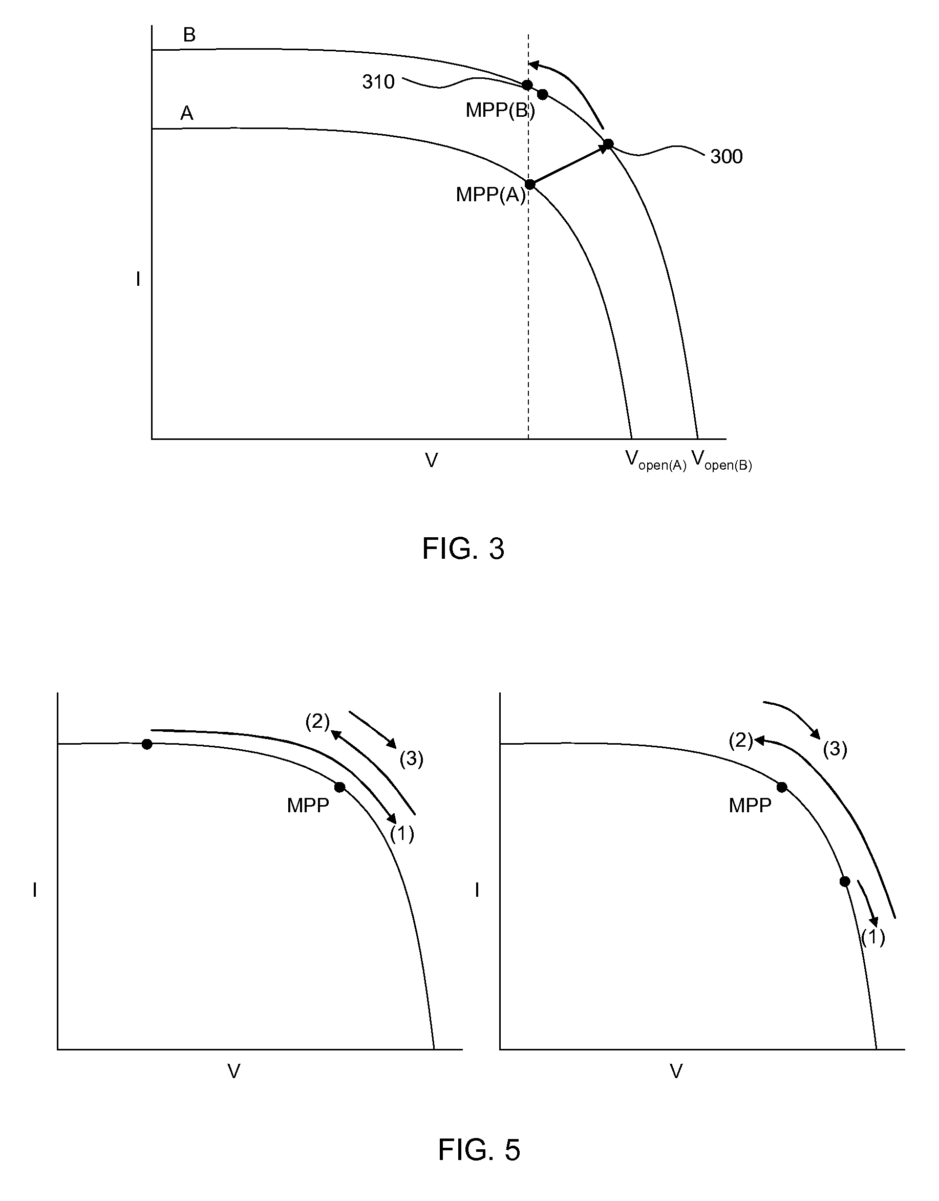
[0037]FIG. 3 schematically depicts an aspect of an embodiment of the MPP tracking method of the present invention;

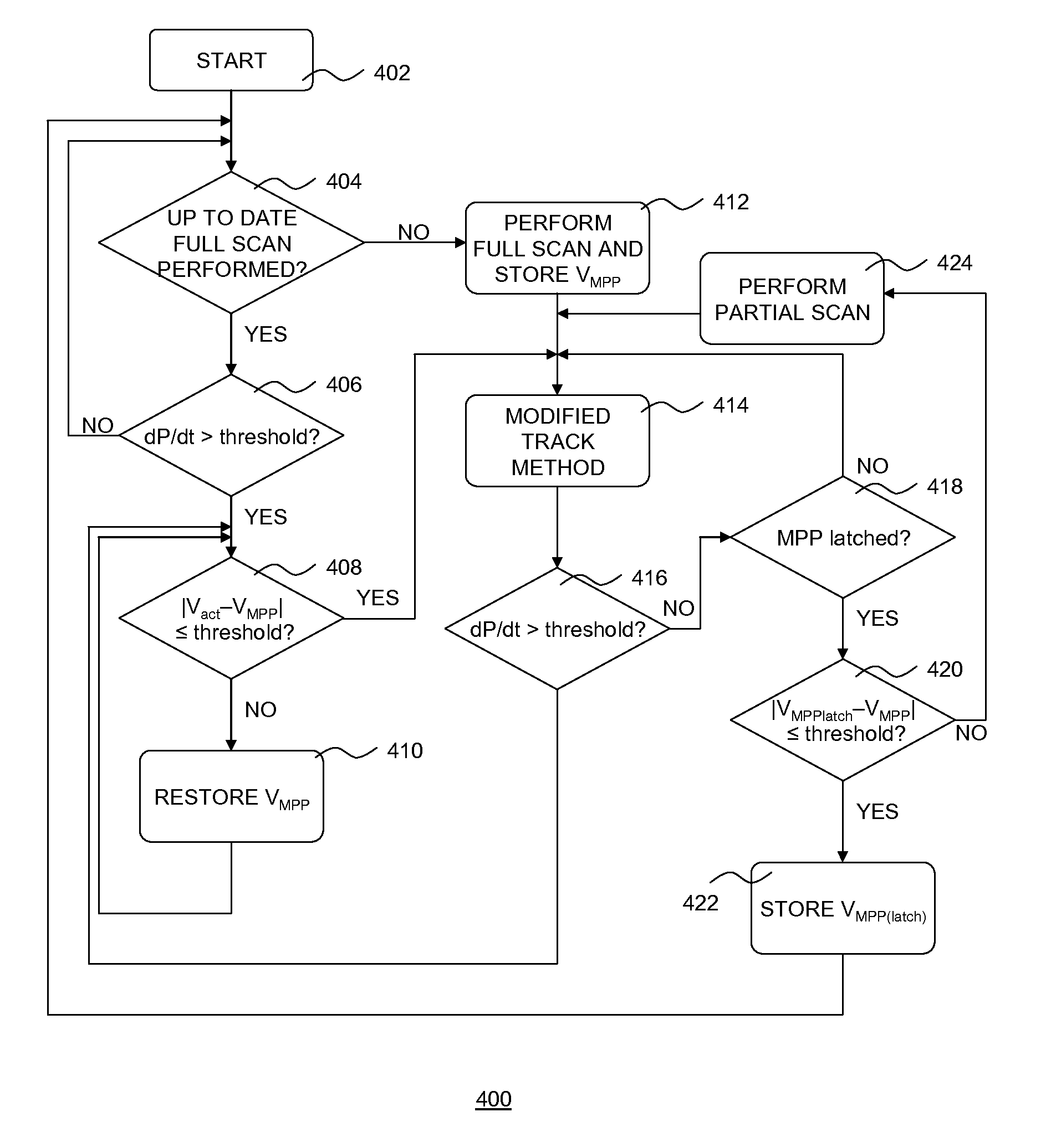
[0038]FIG. 4 schematically depicts another aspect of an embodiment of the MPP tracking method of the present invention; and

[0039]FIG. 5 depicts a flow chart of an embodiment of the method of the present invention.

DETAILED DESCRIPTION OF THE DRAWINGS

[0040]It should be understood that the Figures are merely schematic and are not drawn to scale. It should also be understood that the same reference numerals are used throughout the Figures to indicate the same or similar parts.

[0041]FIG. 2 depicts a typical ...


PUM


Abstract

Consistent with an example embodiment, a method of tracking a maximum power point (MPP) of a PV (photovoltaic) system comprises a circuit with a controller controlling a DC voltage-DC voltage converter for converting an output current of the PV system; the controller further comprises a memory. The method comprises measuring a first value of a PV system voltage at an initial MPP; storing said first value in said memory; periodically sampling a power output level of said PV system, and upon detecting a change in said power output level exceeding a first threshold, reading the first value from the memory; and adjusting a duty cycle of the DC voltage-DC voltage converter until the circuit voltage matches said first value; the method further comprising fine-tuning the duty cycle of the DC voltage-DC voltage converter to a further MPP following detecting a change in said power output level exceeding a first threshold.

Description

[0001]This application claims the priority under 35 U.S.C. §119 of European patent application no. 10164393.0, filed on May 28, 2010, the contents of which are incorporated by reference herein.FIELD OF THE INVENTION[0002]The present invention relates to a method of tracking a maximum power point of a photovoltaic system comprising a circuit including a controller controlling a direct current (DC) voltage to DC voltage converter for converting an output current of the photovoltaic system.[0003]The present invention further relates to a photovoltaic system controller implementing such a method.[0004]The present invention yet further relates to a photovoltaic system comprising such a photovoltaic system controller.BACKGROUND OF THE INVENTION[0005]Renewable energy generation is attracting considerable attention for a number of reasons. Firstly, renewable energy is considered the preferred alternative to fossil fuel based energy generation in order to combat greenhouse gas emissions such...

Claims


Application Information

Patent Timeline
Patent Type & Authority Patents(United States)
IPC IPC(8): H02J1/00G05F1/67
CPCG05F1/67Y02E10/58Y02E10/56
Inventor NAIR, MUKESH BALACHANDRANMURTY, NAGAVOLU SRINIVASABHAT, DATTATREYA SHANKAR
Owner III HLDG 6
Why Eureka
Try Eureka