Device and method for combusting particulate substances
a technology of combusting particulate matter and combustion method, which is applied in the direction of magnetic separation, machines/engines, mechanical apparatuses, etc., can solve the problem of reducing the life of the filter
- Summary
- Abstract
- Description
- Claims
- Application Information
AI Technical Summary
Benefits of technology
Problems solved by technology
Method used
Image
Examples
embodiment
[0048]Representative three embodiments of a combustion device for combusting particulate matters of the present invention will be described in detail with reference to the drawings.
first embodiment
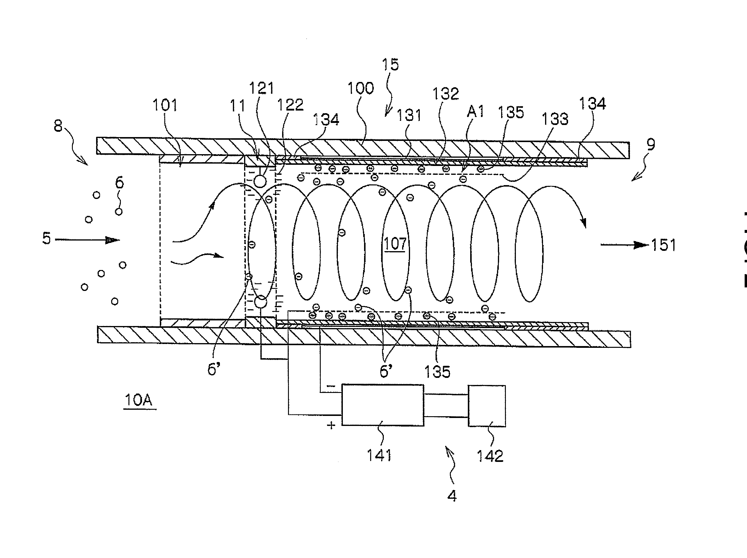
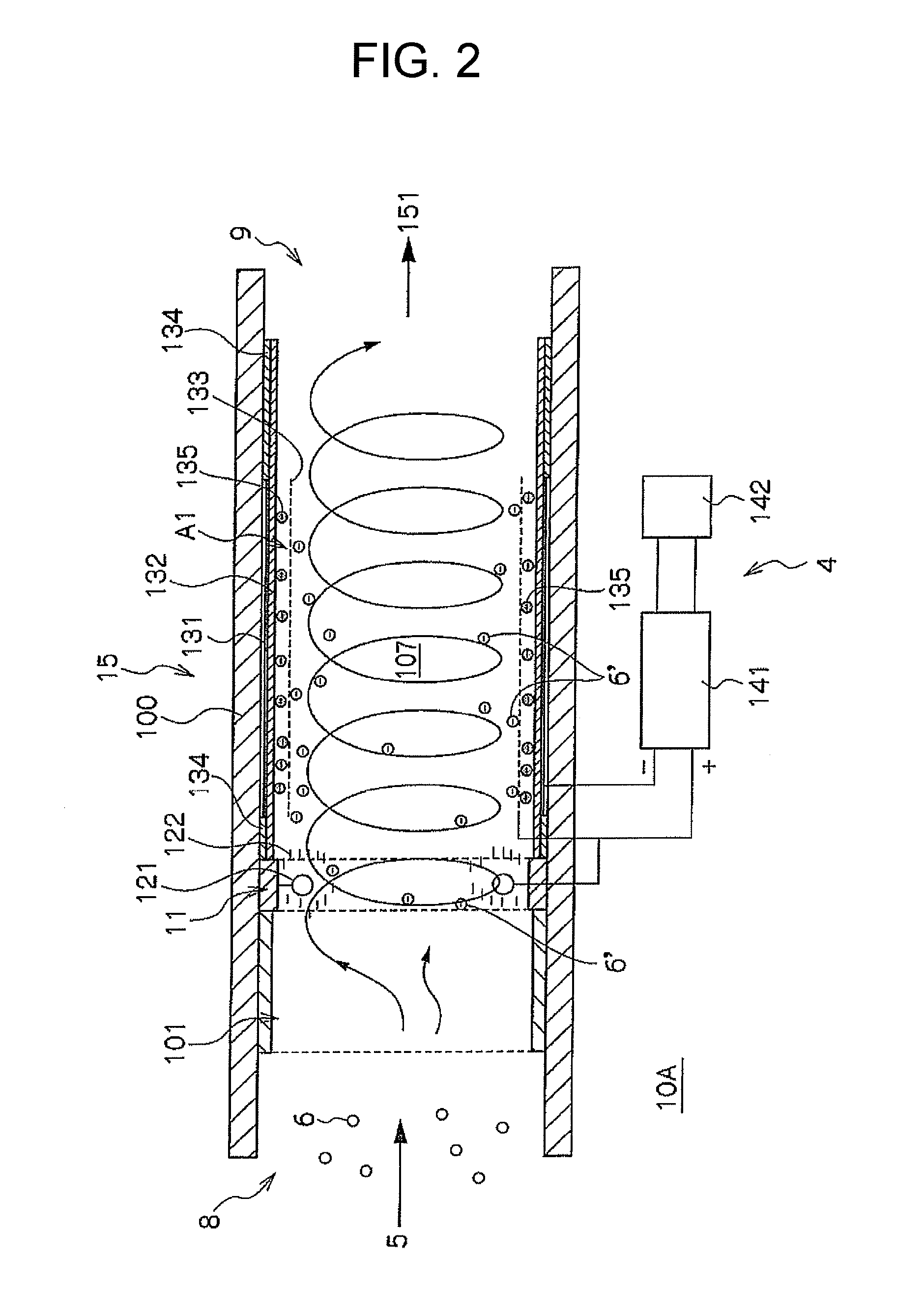
[0049]As shown in FIG. 2, the first embodiment of combustion device 10A for combusting particulate matters is configured so as to electrostatically attract particulate matter 6′ on which negative charge 122 is charged to cylindrical mesh anode 133, which is provided on the downstream side, and to retain particulate matter 6′ at silent discharge area A1, in order to increase the retention time at silent discharge area A1. Specifically, as shown in FIG. 2, the device 10A includes introduction portion 8, charging unit 11, electric discharge unit 15, discharge portion 9 and power source unit 4.
[0050]As shown in FIG. 2, combustion device 10A is preferably configured to have introduction portion 8, charging unit 11, electric discharge unit 15 and discharge portion 9 in the order mentioned toward the downstream side in insulation pipe 100. Each of the portions may be connected to each other as a separate member in the order mentioned toward the downstream side. Further, combustion device 1...
second embodiment
[0075]As shown in FIG. 7, the second embodiment of combustion device 10B for combusting particulate matters is configured so electrostatically attract particulate matter 6′, which has negative charge 222, to cylindrical mesh anode 233 which is provided on the downstream side of the flow channel, and can capture particulate matter 6′ and to deposited particulate matter 6′ on cylindrical mesh anode 233, in order to increase the retention time at silent discharge area A2. Specifically, as shown in FIG. 7, the combustion device 10B includes introduction portion 8, charging unit 21, electric discharge unit 25, discharge portion 9 and power source unit 4 in the order mentioned toward the downstream side. Although, in the example in FIG. 7, charging unit 21 and electric discharge unit 25 are configured as one in insulation pipe 100, charging unit 21 and electric discharge unit 25 may not be necessarily configured as one.
[0076]In the same manner as in the first embodiment, introduction port...
PUM
 Abstract
Description
Claims
Application Information
 - R&D
- Intellectual Property
- Life Sciences
- Materials
- Tech Scout
- Unparalleled Data Quality
- Higher Quality Content
- 60% Fewer Hallucinations
Browse by: Latest US Patents, China's latest patents, Technical Efficacy Thesaurus, Application Domain, Technology Topic, Popular Technical Reports.
© 2025 PatSnap. All rights reserved.Legal|Privacy policy|Modern Slavery Act Transparency Statement|Sitemap|About US| Contact US: help@patsnap.com


